Redscan
The OPTEX REDSCAN is a laser scan detector that can detect a moving object's size, speed, and distance with high-reliability. The integration with HSYCO can be accomplished via direct control through Ethernet connection. The I/O Server complies with the Optex Redscan Protocol v1.71 and has been tested on firmware version 7.3.0.
Redscan Configuration
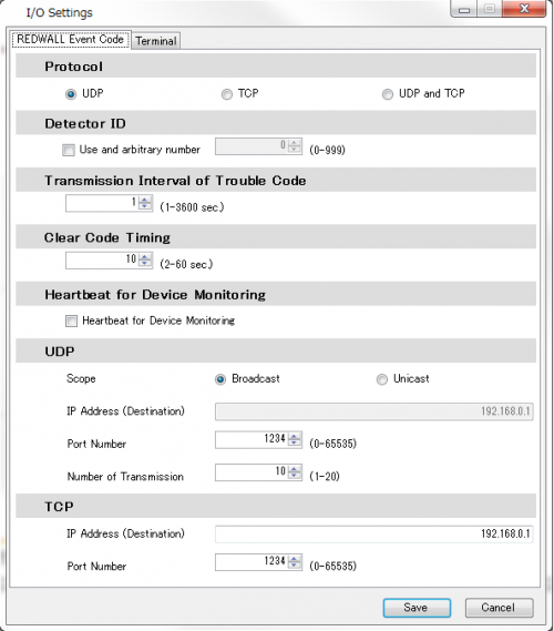
To enable alarm events, make sure the Event Code via Broadcast UPD is enabled. In the Redscan Manager go to Basic Settings > I/O Settings:
To enable the drawing of detected objects on HSYCO's interface, you need to provide the I/O Server with the coordinates of the area that is monitored by the scanner.
To this end, open the Redscan Manager and take note of the upper-left and lower-right corners of the virtual rectangular area covering the detection area set on the scanner:
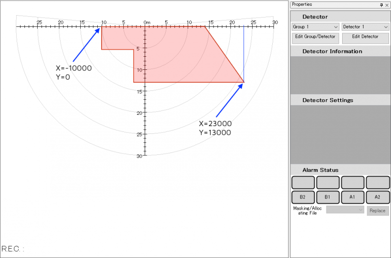
Set the coordinates (in millimeters) of this two points in the I/O Server options 'areaX1', 'areaY1', 'areaX2' and 'areaY2'.
HSYCO Configuration
Add a REDSCAN I/O Server in the I/O Servers section of the Settings and set its parameters:
Communication
- IP Address: host name or IP address of the REDSCAN detector
- IP Port: TCP/IP port to use (as configured on the REDSCAN detector)
High Availability
- Shutdown when inactive: defaults to true.
Options
| ID | Default | Values | Description |
|---|---|---|---|
| eventsport | 1234 | <port_number> | port number to which UDP alarm messages are sent by the scanner. Set to 0 to disable alarm events |
| areax1 | <x> | X coordinate of the upper-left corner of the detection area. If not specified the image is not drawn | |
| areay1 | <y> | Y coordinate of the upper-left corner of the detection area. If not specified the image is not drawn | |
| areax2 | <x> | X coordinate of the lower-right corner of the detection area. If not specified the image is not drawn | |
| areay2 | <y> | Y coordinate of the lower-right corner of the detection area. If not specified the image is not drawn | |
| flipx | false | true | the detected objects image is flipped horizontally |
| false | the image is not flipped horizontally | ||
| flipy | false | true | the detected objects image is flipped vertically |
| false | the image is not flipped vertically | ||
| bordercolor | red | <color> | color for the border of the circles representing the detected objects. If the color string contains commas, replace them with colons (e.g. 255,10,10 becomes 255:10:10) |
| fillcolor | white | <color> | color for the inner part of the circles representing the detected objects. If the color string contains commas, replace them with colons (e.g. 255,10,10 becomes 255:10:10) |
| detectioninterval | 10 | 0 ≤ n ≤ 100 | interval between detection reports sent by the scanner. 1 = 50ms, 100 = 5sec. Set to 0 to disable detection events |
Datapoints
| ID | Value | R/W | Description |
|---|---|---|---|
| connection | online | R | connection established |
| offline | R | HSYCO can't connect to the scanner | |
| version | <version> | R | Firmware version of the scanner, e.g. "7.3.0" |
| detected | <array> | R | JSON array with the list of detected objects. See here for details |
| alarm.latest | <area> | R | latest area in which there is an active alarm, e.g. "A1" or "B2". |
| <empty_string> | R | no active alarms | |
| alarm.disq | 0 | R | Disqualification circuit restored |
| 1 | R | Disqualification circuit active | |
| alarm.antirot | 0 | R | Anti-rotation function restored |
| 1 | R | Anti-rotation function active | |
| alarm.antimask | 0 | R | Anti-masking function restored |
| 1 | R | Anti-masking function active | |
| alarm.sensor | 0 | R | Sensor error condition restored |
| 1 | R | Sensor error condition | |
| alarm.dirt | 0 | R | Laser window OK |
| 1 | R | Dirt on the laser window (Self check function) | |
| alarm.tamper | 0 | R | Tamper circuit restored |
| 1 | R | Tamper circuit active |
Detected objects format
When no object is detected the value of the 'detected' datapoint is an empty JSON array:
[]
When there are objects detects, it has the following format:
   [
        {
            "x":512,
            "y":5622,
            "ox":8565,
            "oy":4421,
            "w":229
        },
        {
            "x":1040,
            "y":2283,
            "ox":1754,
            "oy":3987,
            "w":194
        }
    ]
The above example corresponds to the detection of two objects. Each object has the following attributes:
- x: X coordinate of the object's current position
- y: Y coordinate of the object's current position
- ox: X coordinate of the object's position when the alarm was initially triggered
- oy: Y coordinate of the object's position when the alarm was initially triggered
- w: current width of the detected object
User Interface
If the detection area coordinates are specified in the I/O Server options, the driver will be able to draw the detected objects on an [[Image]] object.
To this end, just add an Image to your project and set its ID to "<IOServer_ID>.area" (e.g. "redscan.area"). You can place this image on top of another image representing the monitored area to see the objects moving over it.
Release Notes
3.6.0
- initial version release
OPTEX and REDSCAN are registered trademarks of OPTEX INC.