Contatto
The CONTATTO system is DUEMMEGI’s proprietary bus architecture for building automation. HSYCO fully integrates with this system through the MCP control and gateway module, and its FXP-XT serial communication protocol.
A serial connection between the MCPXT and the HSYCO SERVER is required for the integration, either directly through the server’s RS-232 port or via the RS-232 port of a supported serial to IP gateway, including the WEBS module.
The MCP4 can be connected via the integrated serial to IP gateway.
The Contatto I/O Server requires MCP-XT firmware version 3.0 or later. The MCPIDE configuration tools pass-through support for secure access to the MCP via HSYCO requires MCPIDE version 3.2.3 or later.
Communication
Use a DE-9 (often called DB-9) male-female RS-232 straight cable to connect the RS-232 MCPXT port to the serial port on HSYCO SERVER or serial gateway. You can also connect the MCPXT using the RS-485 port. The MCP4 can also be connected via the integrated serial to IP gateway.
RS-232 parameters:
| Baud rate | 9600, 38400, 57600 or 115200 bps (according to the MCP serial port setting) |
| Data bits | 8 |
| Stop bit | 1 |
| Parity | none |
| Flow control | none |
A speed of 115200 bps is recommended to achieve good performance, particularly when the number of devices connected to the bus is large.
High Availability
- Shutdown when inactive: defaults to false.
HSYCO Configuration
You can define and connect to more than one CONTATTO bus using several MCP gateways.
The CONTATTO I/O Server also supports dual, redundant connections between HSYCO and MCP.
If the main connection fails, HSYCO automatically re-routes the communication with MCP through the fail-over connection.
Options
| ID | Default | Values | Description |
|---|---|---|---|
| startupevents | false | true | generate IO events also during the driver’s start-up phase |
| false | start generating events only after HSYCO is aligned with the current status of the system | ||
| inputdiscovery | false | true | auto-detects CONTATTO’s input devices as configured in the MCP, and automatically creates the list of all detected devices and individual data points in the systemtopo.txt file. Should be enabled to allow the automatic update of (button) objects’ states |
| false | auto-detect for input devices is disabled | ||
| outputdiscovery | true | true | auto-detects CONTATTO’s output devices as configured in the MCP, and automatically creates the list of all detected devices and individual data points in the systemtopo.txt file. Should be enabled to allow the automatic update of (button) objects’ states |
| false | auto-detect for output devices is disabled | ||
| virtualdiscovery | false | true | auto-detects CONTATTO’s virtual points for input and output devices as configured in the MCP, and automatically creates the list of all detected virtual data points in the systemtopo.txt file. Should be enabled to allow the automatic update of (button) objects’ states |
| false | auto-detect for devices’ virtual data points is disabled | ||
| virtualpoints | false | 1 ... 2032 | enables polling for the first n virtual points of the MCP. Enable this option only if you need to generate I/O events based on these virtual points |
| true | enables polling for all the 2032 virtual points of the MCP | ||
| false | polling of the MCP virtual data points is disabled | ||
| registers | false | 1 ... 1024 | enables polling for registers R0-Rn of the MCP. Enable this option only if you need to generate I/O events based on these registers |
| true | enables polling for registers R0-R127 of the MCP | ||
| false | polling of the MCP registers is disabled | ||
| powerdisplay | false | ≥ 0 (MODANA address) | enables the automatic display in the GUI of the total real power measured by a MODANA or MODANAM module connected to this MCP. Note that, if you have more than one MCP gateway, you should enable this option for one gateway only |
| false | power display disabled for this MCP | ||
| disablemodhtpulsereset | false | true | disables automatic reset of MODHT pulse outputs (panic.reset, dnd.reset, service.reset, fan) |
| false | MODHT pulse outputs are automatically reset to 0 when found at level 1 | ||
| powersensivity | 50 | ≥ 0 | measured power changes are reported only if the difference from last reading is equal or greater than the power sensivity option, in Watts |
| detectevents | false | true | generate forced events when a device is detected at start-up |
| false | do not generate events when a device is detected at start-up | ||
| toolspassword | string | set this option with a long string (only letters and numbers) password to allow the remote connection of MCP-IDE and other configuration tools to the MCP gateways that are connected to HSYCO. For additional security, it is recommended to set this option only when required | |
| language | english | en it fr | language for all messages from the CONTATTO system: English, Italian or French |
Initialization and Connection Events
| Event name | Value | Description |
|---|---|---|
| connection | online | connection established to the MCP module |
| offline | HSYCO can’t connect to the MCP module | |
| detected.input.<n>.<s> | model name | an input device of the type passed as value has been detected at address <n>, using <s> addresses |
| detected.output.<n>.<s> | model name | an output device of the type passed as value has been detected at address <n>, using <s> addresses |
The Device Configuration Database
The systemtopo.txt file contains the list of all devices and their individual input, output and virtual data points that could be directly associated to graphic object in the Web-based user interface. This file can be filled manually or automatically by HSYCO at start-up.
To enable automatic discovery and automatic generation of devices’ information in the systemtopo file, use the inputdiscovery, outputdiscovery and virtualdiscovery options in Settings. The default behavior is to only discover devices with output data points.
This is an example of an automatically generated systemtopo.txt file:
(devices)
contatto.o10.1 : LIGHT ; LIGHT
contatto.o6.1 : LIGHT ; DIMMER
contatto.o7.2 : LIGHT ; LIGHT
contatto.o7.1 : LIGHT ; DIMMER
contatto.o9.2 : AUTOM ; VSHUT
contatto.o5.4 : LIGHT ; LIGHT
contatto.o9.1 : AUTOM ; VSHUT
contatto.o5.3 : LIGHT ; LIGHT
contatto.o5.2 : LIGHT ; LIGHT
contatto.o5.1 : LIGHT ; LIGHT
You should then manually add comments and other optional parameters:
(devices)
contatto.o10.1 : LIGHT ; LIGHT; main entrance light
contatto.o6.1 : LIGHT ; DIMMER; lobby dimmer
contatto.o7.2 : LIGHT ; LIGHT; kitchen workbench
contatto.o7.1 : LIGHT ; DIMMER; kitchen main dimmer
MCP Data Points
The MCP implements 2032 virtual points for binary (on/off) data and 1024 registers and counters for positive scalar values (0-65535). All virtual points, registers and counters can optionally generate I/O events. You can also write to the virtual data points, registers and counters using the IO action in EVENTS or ioSet() method in Java.
You cannot directly control the MCP virtual data points, registers or counters using GUI objects.
To enable polling of the current state of the MCP’s virtual data points, enable the virtualpoints options in hsyco.ini.
To enable polling of the current state of the MCP’s registers, enable the registers options in hsyco.ini.
To enable polling of the current state of the MCP’s counters, enable the counters options in hsyco.ini.
If you only have to write to virtual points, registers or counters, enabling polling is not strictly required.
| ID | Value | R/W | Description |
|---|---|---|---|
| busfault | 0 | R | no bus fault detected |
| 1 | R | bus fault detected | |
| modulefault | 0 | R | no modules fault detected |
| 1 | R | modules fault detected | |
| v0.<n> | 0 | RW | virtual data point <n> off (<n>: 1-2032) |
| 1 | RW | virtual data point <n> on (<n>: 1-2032) | |
| r0.<n> | <x> | RW | register <n> (<n>: 0-1023) set to value <x> (<x>: 0-65535) |
| c0.<n> | <x> | RW | counter <n> (<n>: 0-1023) set to value <x> (<x>: 0-65535) |
MCP Internal Clock
The MCP module has an integrated real-time clock. You can use the clock datapoint to read the MCP date and time, and set the MCP clock to HSYCO’s current time.
| ID | Value | R/W | Description |
|---|---|---|---|
| clock | yyyy-mm-dd hh:mm:ss | R | the MCP clock current time |
| read | W | read the MCP clock, and the delta with HSYCO’s time | |
| sync | W | set the MCP clock to HSYCO’s current time | |
| clock.delta | integer number | R | the delta time in seconds between the MCP and HSYCO clocks. A positive number means that the MCP clock is ahead of HSYCO |
CONTATTO Modules Events and Control
Each CONTATTO module has its own set of read-only or read-write data points, mapping the specific set of features.
All modules also have a read-only "fault" data point, set to 1 if the MCP has detected a module fault condition, or 0 if the module is working normally.
| ID | Value | R/W | Description |
|---|---|---|---|
| i<address>.fault | 0 | R | input module working normally |
| 1 | R | input module fault detected | |
| o<address>.fault | 0 | R | output module working normally |
| 1 | R | output module fault detected |
| Module Code | Description |
|---|---|
| MOD8I/A | 8 digital input module for NO contacts in modular housing |
| MOD32I/A | 32 digital input module for NO contacts in modular housing |
| MOD32IL | 32 digital input module for NO contacts in modular housing |
| MOD32IN | 32 digital input module for NO contacts in modular housing |
| MOD8INP2/A | 8 digital input module for NO contacts |
| MOD8INP2/C | 8 digital input module for NC contacts |
| MOAN/I | 0÷10V analog input module |
| MOAN/I4 | quad 0÷10V analog input module |
| MI420 | 4÷20mA analog input module |
| MI420-X4 | quad 4÷20mA analog input module |
| MOD4AM12/V/I | 4-channel 0÷10V or 4÷20mA (0÷21mA) analog input module |
| MOD2PT | input module for two PT100 temperature probes |
| MODCNT | 4-channel counter module in modular housing |
| MODNTC | input module for ambient temperature sensors and potentiometers |
| MOD4I/A | 4-digital input module for NO contacts in modular housing |
| MOD4I/S | 4-digital input module for NO contacts in 2M modular housing |
| MODLUX | ambient light measurement module with sensor for ceiling mounting |
| MODMETEO | meteorological data detection module for Contatto bus |
| MOD8R | 8 power relay output module |
| MODPNP | 8 positive logic (PNP) open collector digital output module |
| MODREL | 8 relay output compact module in DIN 3M housing |
| MOAN/U | 0÷10V analog output module |
| MO420 | 4÷20mA analog output module |
| MODLC, MODLC-P | ambient light regulator module with integrated sensor |
| MOD4-4S | 4 digital input and 4 power relay output multifunction module |
| MOD2-2R | 2 digital input and 2 power relay output module |
| MOD4-4 | 4 digital input and 4 digital output module |
| MOD2DM | 2x300W dimmer module |
| MOD2DV | dual 1-10V output for electronic ballast driving |
| MOD8IL | 8 digital input – 8 LED output module for wall box |
| MOD4DV | quad 0-10V output module for generic applications or for external dimmers control |
| MODDMX | DMX gateway |
| MODDALI | 4-channel DALI gateway |
| MODDALI8 | 8-channel broadcast DALI gateway |
| CLIMA2 | module for the regulation of the ambient temperature |
| MODANA | network analyzer module |
| MODANAM | network analyzer module |
| MODPQ5 | tags proximity reader and programmer |
| MODHT | hotel room controller |
| MODCA | access control module |
| MODKB | keypad access control module |
| MODDI | 500W IGBT dimmer module |
| MODCL | temperature control module |
| MOD4TP/I | 8 digital input and 4 roller shutters or blinds with detection of travel time |
| MODRHT | Temperature, relative humidity and dew point sensor |
| MODAM2 | Multi-function, 2 inputs analog module |
| MODIGLASS, MODIGLASS3 | 6 button touch keypad |
| MODAURORA | 6 button touch 6 button touch keypad with optional temperature and humidity sensor |
| MODSENSE-CO2 | Environmental monitor, with CO2, temperature, humidity, dew point, light level and sound level sensors |
| MODSUN | Light sensor |
MOD8I/A
8 digital input module for NO contacts in modular housing.
It uses one input address in the CONTATTO bus.
| ID | Value | R/W | Description |
|---|---|---|---|
| i<address>.1 | 0 | R | input pin 1 off |
| 1 | R | input pin 1 on | |
| i<address>.2 | 0 | R | input pin 2 off |
| 1 | R | input pin 2 on | |
| i<address>.3 | 0 | R | input pin 3 off |
| 1 | R | input pin 3 on | |
| i<address>.4 | 0 | R | input pin 4 off |
| 1 | R | input pin 4 on | |
| i<address>.5 | 0 | R | input pin 5 off |
| 1 | R | input pin 5 on | |
| i<address>.6 | 0 | R | input pin 6 off |
| 1 | R | input pin 6 on | |
| i<address>.7 | 0 | R | input pin 7 off |
| 1 | R | input pin 7 on | |
| i<address>.8 | 0 | R | input pin 8 off |
| 1 | R | input pin 8 on |
MOD32I/A
32 digital input module for NO contacts in modular housing.
It uses four addresses of the Contatto bus, one for each group of 8 inputs.
| ID | Value | R/W | Description |
|---|---|---|---|
| i<address>.1 | 0 | R | input pin 1 off |
| 1 | R | input pin 1 on | |
| i<address>.2 | 0 | R | input pin 2 off |
| 1 | R | input pin 2 on | |
| i<address>.3 | 0 | R | input pin 3 off |
| 1 | R | input pin 3 on | |
| i<address>.4 | 0 | R | input pin 4 off |
| 1 | R | input pin 4 on | |
| i<address>.5 | 0 | R | input pin 5 off |
| 1 | R | input pin 5 on | |
| i<address>.6 | 0 | R | input pin 6 off |
| 1 | R | input pin 6 on | |
| i<address>.7 | 0 | R | input pin 7 off |
| 1 | R | input pin 7 on | |
| i<address>.8 | 0 | R | input pin 8 off |
| 1 | R | input pin 8 on | |
| i<address+1>.1 | 0 | R | input pin 1 off |
| 1 | R | input pin 1 on | |
| i<address+1>.2 | 0 | R | input pin 2 off |
| 1 | R | input pin 2 on | |
| i<address+1>.3 | 0 | R | input pin 3 off |
| 1 | R | input pin 3 on | |
| i<address+1>.4 | 0 | R | input pin 4 off |
| 1 | R | input pin 4 on | |
| i<address+1>.5 | 0 | R | input pin 5 off |
| 1 | R | input pin 5 on | |
| i<address+1>.6 | 0 | R | input pin 6 off |
| 1 | R | input pin 6 on | |
| i<address+1>.7 | 0 | R | input pin 7 off |
| 1 | R | input pin 7 on | |
| i<address+1>.8 | 0 | R | input pin 8 off |
| 1 | R | input pin 8 on | |
| i<address+2>.1 | 0 | R | input pin 1 off |
| 1 | R | input pin 1 on | |
| i<address+2>.2 | 0 | R | input pin 2 off |
| 1 | R | input pin 2 on | |
| i<address+2>.3 | 0 | R | input pin 3 off |
| 1 | R | input pin 3 on | |
| i<address+2>.4 | 0 | R | input pin 4 off |
| 1 | R | input pin 4 on | |
| i<address+2>.5 | 0 | R | input pin 5 off |
| 1 | R | input pin 5 on | |
| i<address+2>.6 | 0 | R | input pin 6 off |
| 1 | R | input pin 6 on | |
| i<address+2>.7 | 0 | R | input pin 7 off |
| 1 | R | input pin 7 on | |
| i<address+2>.8 | 0 | R | input pin 8 off |
| 1 | R | input pin 8 on | |
| i<address+3>.1 | 0 | R | input pin 1 off |
| 1 | R | input pin 1 on | |
| i<address+3>.2 | 0 | R | input pin 2 off |
| 1 | R | input pin 2 on | |
| i<address+3>.3 | 0 | R | input pin 3 off |
| 1 | R | input pin 3 on | |
| i<address+3>.4 | 0 | R | input pin 4 off |
| 1 | R | input pin 4 on | |
| i<address+3>.5 | 0 | R | input pin 5 off |
| 1 | R | input pin 5 on | |
| i<address+3>.6 | 0 | R | input pin 6 off |
| 1 | R | input pin 6 on | |
| i<address+3>.7 | 0 | R | input pin 7 off |
| 1 | R | input pin 7 on | |
| i<address+3>.8 | 0 | R | input pin 8 off |
| 1 | R | input pin 8 on |
MOD32IL
32 digital input module for NO contacts in modular housing.
It uses one addresses of the Contatto bus and four channels, one for each group of 8 inputs.
| ID | Value | R/W | Description |
|---|---|---|---|
| i<address>.N N=1-32 | 0 | R | input pin N off |
| 1 | R | input pin N on |
MOD32IN
32 digital input module for NO contacts in modular housing.
It uses one addresses of the Contatto bus and four channels, one for each group of 8 inputs.
| ID | Value | R/W | Description |
|---|---|---|---|
| i<address>.N N=1-32 | 0 | R | input pin N off |
| 1 | R | input pin N on |
MOD8INP2/A
8 digital input module for NO contacts.
It uses one input address of the Contatto bus.
| ID | Value | R/W | Description |
|---|---|---|---|
| i<address>.1 | 0 | R | input pin 1 off |
| 1 | R | input pin 1 on | |
| i<address>.2 | 0 | R | input pin 2 off |
| 1 | R | input pin 2 on | |
| i<address>.3 | 0 | R | input pin 3 off |
| 1 | R | input pin 3 on | |
| i<address>.4 | 0 | R | input pin 4 off |
| 1 | R | input pin 4 on | |
| i<address>.5 | 0 | R | input pin 5 off |
| 1 | R | input pin 5 on | |
| i<address>.6 | 0 | R | input pin 6 off |
| 1 | R | input pin 6 on | |
| i<address>.7 | 0 | R | input pin 7 off |
| 1 | R | input pin 7 on | |
| i<address>.8 | 0 | R | input pin 8 off |
| 1 | R | input pin 8 on |
MOD8INP2/C
8 digital input module for NC contacts.
It uses one input address of the Contatto bus.
| ID | Value | R/W | Description |
|---|---|---|---|
| i<address>.1 | 0 | R | input pin 1 off |
| 1 | R | input pin 1 on | |
| i<address>.2 | 0 | R | input pin 2 off |
| 1 | R | input pin 2 on | |
| i<address>.3 | 0 | R | input pin 3 off |
| 1 | R | input pin 3 on | |
| i<address>.4 | 0 | R | input pin 4 off |
| 1 | R | input pin 4 on | |
| i<address>.5 | 0 | R | input pin 5 off |
| 1 | R | input pin 5 on | |
| i<address>.6 | 0 | R | input pin 6 off |
| 1 | R | input pin 6 on | |
| i<address>.7 | 0 | R | input pin 7 off |
| 1 | R | input pin 7 on | |
| i<address>.8 | 0 | R | input pin 8 off |
| 1 | R | input pin 8 on |
MOAN/I
0÷10V analog input module.
It uses one input address in the range 1 to 127 of the Contatto bus.
| ID | Value | R/W | Description |
|---|---|---|---|
| i<address>.1 | 0 ... 255 | R | voltage value divided in 255 steps |
MOAN/I4
Quad 0÷10V analog input module.
It uses four consecutive addresses of the Contatto bus, one for each input.
| ID | Value | R/W | Description |
|---|---|---|---|
| i<address>.1 | 0 ... 255 | R | voltage value divided in 255 steps |
| i<address+1>.1 | 0 ... 255 | R | voltage value divided in 255 steps |
| i<address+2>.1 | 0 ... 255 | R | voltage value divided in 255 steps |
| i<address+3>.1 | 0 ... 255 | R | voltage value divided in 255 steps |
MI420
4÷20mA analog input module.
It uses one input address in the range 1 to 127 of the Contatto bus.
| ID | Value | R/W | Description |
|---|---|---|---|
| i<address>.1 | 0 ... 255 | R | current value divided in 255 steps |
MI420-X4
Quad 4÷20mA analog input module.
It uses four consecutive addresses of the Contatto bus, one for each input.
| ID | Value | R/W | Description |
|---|---|---|---|
| i<address>.1 | 0 ... 255 | R | current value divided in 255 steps |
| i<address+1>.1 | 0 ... 255 | R | current value divided in 255 steps |
| i<address+2>.1 | 0 ... 255 | R | current value divided in 255 steps |
| i<address+3>.1 | 0 ... 255 | R | current value divided in 255 steps |
MOD4AM12/V/I
4-channel 0÷10V or 4÷20mA (0÷21mA) analog input module.
It uses one input address of the Contatto bus.
| ID | Value | R/W | Description |
|---|---|---|---|
| i<address>.1 | 0 ... 4095 | R | measurement range divided in 4095 steps |
| i<address>.2 | 0 ... 4095 | R | measurement range divided in 4095 steps |
| i<address>.3 | 0 ... 4095 | R | measurement range divided in 4095 steps |
| i<address>.4 | 0 ... 4095 | R | measurement range divided in 4095 steps |
MOD2PT
Input module for two PT100 temperature probes.
It uses one or two addresses according to how the dip-switch is set.
If both channels are enabled (IN1 and IN2), setting the n base address through the FXPRO programmer, the input address and address+1 (consecutive) will be automatically assigned to the module.
| ID | Value | R/W | Description |
|---|---|---|---|
| i<address>.1 | 0 ... 255 | R | range –40 ÷ +87.5°C: code 0 corresponds to –40°C and code 255 corresponds to +87.5°C |
| i<address+1>.1 | 0 ... 255 | R | range –40 ÷ +87.5°C: code 0 corresponds to –40°C and code 255 corresponds to +87.5°C |
MODCNT
4-channel counter module in modular housing.
It uses one input address of the Contatto bus.
| ID | Value | R/W | Description |
|---|---|---|---|
| i<address>.1 | 0 ... 65535 | R | number of pulses |
| i<address>.2 | 0 ... 65535 | R | number of pulses |
| i<address>.3 | 0 ... 65535 | R | number of pulses |
| i<address>.4 | 0 ... 65535 | R | number of pulses |
MODNTC
Input module for ambient temperature sensors and potentiometers.
It uses one input address of the Contatto bus.
The temperature values measured by MODNTC module are reported as Kelvin degrees multiplied by 10; in other words, 0°C will be reported as 2730, 0.1°C will be reported as 2731 and so on.
Concerning the potentiometer channels, the values read from the module will be 0 with the potentiometer at its minimum position and it will be 1000 with the potentiometer at its maximum position.
| ID | Value | R/W | Description |
|---|---|---|---|
| i<address>.1 | 0 ... 4095 | R | temperature value |
| i<address>.2 | 0 ... 4095 | R | temperature value |
| i<address>.3 | 0 ... 4095 | R | temperature value |
| i<address>.4 | 0 ... 4095 | R | temperature value |
MOD4I/A
4-digital input module for NO contacts in modular housing.
It uses one input address in the range 1 to 127 of the Contatto bus.
| ID | Value | R/W | Description |
|---|---|---|---|
| i<address> | 0 | R | input pin 1 off |
| 1 | R | input pin 1 on | |
| i<address+1> | 0 | R | input pin 1 off |
| 1 | R | input pin 1 on | |
| i<address+2> | 0 | R | input pin 1 off |
| 1 | R | input pin 1 on | |
| i<address+3> | 0 | R | input pin 1 off |
| 1 | R | input pin 1 on |
MOD4I/S
4-digital input module for NO contacts in 2M modular housing.
It uses one address of the Contatto bus.
| ID | Value | R/W | Description |
|---|---|---|---|
| i<address> | 0 | R | input pin 1 off |
| 1 | R | input pin 1 on | |
| i<address+1> | 0 | R | input pin 1 off |
| 1 | R | input pin 1 on | |
| i<address+2> | 0 | R | input pin 1 off |
| 1 | R | input pin 1 on | |
| i<address+3> | 0 | R | input pin 1 off |
| 1 | R | input pin 1 on |
MODLUX
Ambient light measurement module with sensor for ceiling mounting.
It uses one address of the Contatto bus.
| ID | Value | R/W | Description |
|---|---|---|---|
| i<address>.1 | 0 ... 1023 | R | ambient brightness value |
MODMETEO
Meteorological data detection module for Contatto bus.
It uses one input address and, if enabled by the configuration panel of MCP IDE, one output address with the same value.
| ID | Value | R/W | Description |
|---|---|---|---|
| i<address>.temp | <temp> | R | temperature value (in C/10) |
| i<address>.lux | <lux*10> | R | daylight value in tens of LUX |
| i<address>.wind | 1 m/s / 10 | R | wind speed value |
| i<address>.rain | 0 | R | no rain |
| 1 | R | rain | |
| i<address>.night | 0 | R | day |
| 1 | R | night | |
| i<address>.temp.limit | 0 | R | measured temperature < threshold |
| 1 | R | measured temperature > threshold | |
| i<address>.lux.limit | 0 | R | measured daylight < threshold |
| 1 | R | measured daylight > threshold | |
| i<address>.wind.limit | 0 | R | measured wind speed < threshold |
| 1 | R | measured wind speed > threshold | |
| i<address>.light.south | 0 | R | light not from South |
| 1 | R | light from South | |
| i<address>.light.west | 0 | R | light not from West |
| 1 | R | light from West | |
| i<address>.light.east | 0 | R | light not from East |
| 1 | R | light from East | |
| i<address>.fault | 0 | R | sensor works correctly |
| 1 | R | sensor failure | |
| o<address>.temp | <temp> | RW | temperature threshold (in C/10) |
| off | RW | temperature threshold off | |
| o<address>.lux | <lux*10> | RW | daylight threshold |
| off | RW | daylight threshold off | |
| o<address>.wind | 1 m/s / 10 | RW | wind speed threshold |
| off | RW | wind speed threshold off |
MOD8R
8 power relay output module.
It uses one output address of the Contatto bus.
| ID | Value | R/W | Description |
|---|---|---|---|
| o<address>.1 | 0 | RW | output pin 1 off |
| 1 | RW | output pin 1 on | |
| o<address>.2 | 0 | RW | output pin 2 off |
| 1 | RW | output pin 2 on | |
| o<address>.3 | 0 | RW | output pin 3 off |
| 1 | RW | output pin 3 on | |
| o<address>.4 | 0 | RW | output pin 4 off |
| 1 | RW | output pin 4 on | |
| o<address>.5 | 0 | RW | output pin 5 off |
| 1 | RW | output pin 5 on | |
| o<address>.6 | 0 | RW | output pin 6 off |
| 1 | RW | output pin 6 on | |
| o<address>.7 | 0 | RW | output pin 7 off |
| 1 | RW | output pin 7 on | |
| o<address>.8 | 0 | RW | output pin 8 off |
| 1 | RW | output pin 8 on |
You can also set the value to on or off, that is equivalent to 1 and 0.
MODPNP
8 positive logic (PNP) open collector digital output module.
It uses one output address in the range 1 to 127 of the Contatto bus.
| ID | Value | R/W | Description |
|---|---|---|---|
| o<address>.1 | 0 | RW | output pin 1 off |
| 1 | RW | output pin 1 on | |
| o<address>.2 | 0 | RW | output pin 2 off |
| 1 | RW | output pin 2 on | |
| o<address>.3 | 0 | RW | output pin 3 off |
| 1 | RW | output pin 3 on | |
| o<address>.4 | 0 | RW | output pin 4 off |
| 1 | RW | output pin 4 on | |
| o<address>.5 | 0 | RW | output pin 5 off |
| 1 | RW | output pin 5 on | |
| o<address>.6 | 0 | RW | output pin 6 off |
| 1 | RW | output pin 6 on | |
| o<address>.7 | 0 | RW | output pin 7 off |
| 1 | RW | output pin 7 on | |
| o<address>.8 | 0 | RW | output pin 8 off |
| 1 | RW | output pin 8 on |
You can also set the value to on or off, that is equivalent to 1 and 0.
MODREL
8 relay output compact module in DIN 3M housing.
It uses one output address in the range 1 to 127 of the Contatto bus.
| ID | Value | R/W | Description |
|---|---|---|---|
| o<address>.1 | 0 | RW | output pin 1 off |
| 1 | RW | output pin 1 on | |
| o<address>.2 | 0 | RW | output pin 2 off |
| 1 | RW | output pin 2 on | |
| o<address>.3 | 0 | RW | output pin 3 off |
| 1 | RW | output pin 3 on | |
| o<address>.4 | 0 | RW | output pin 4 off |
| 1 | RW | output pin 4 on | |
| o<address>.5 | 0 | RW | output pin 5 off |
| 1 | RW | output pin 5 on | |
| o<address>.6 | 0 | RW | output pin 6 off |
| 1 | RW | output pin 6 on | |
| o<address>.7 | 0 | RW | output pin 7 off |
| 1 | RW | output pin 7 on | |
| o<address>.8 | 0 | RW | output pin 8 off |
| 1 | RW | output pin 8 on |
You can also set the value to on or off, that is equivalent to 1 and 0.
MOAN/U
0÷10V analog output module.
It uses one output address in the range 1 to 127 of the Contatto bus.
| ID | Value | R/W | Description |
|---|---|---|---|
| o<address> | x/255 | R | value in fractional format, where 0 ≤ x ≤ 255 |
| o<address> | <x%> | W | the percentage of signal (0÷100%) applied to the output |
| 0...255 | W | convert the 8 bits digital code received through the bus in the proper analog level. | |
| x/y | W | fractional format, formatted as x/y, where 0 ≤ x ≤ y |
MO420
4÷20mA analog output module.
It uses one output address in the range 1 to 127 of the Contatto bus.
| ID | Value | R/W | Description |
|---|---|---|---|
| o<address> | <x%> | RW | the percentage of signal (0÷100%) applied to the output |
| 0...255 | RW | convert the 8 bits digital code received through the bus in the proper analog level | |
| x/y | RW | fractional format, formatted as x/y, where 0 ≤ x ≤ y |
MODLC and MODLC-P
Ambient light regulator module with integrated sensor.
It uses one input address and, if enabled by the configuration panel of MCP IDE, one output address with the same value.
| ID | Value | R/W | Description |
|---|---|---|---|
| i<address>.lux | value equivalent to three times the brightness in lux detected by the sensor | R | the brightness value in lux detected by the MODLC |
| i<address>.level | calculated value for the automatic brightness regulation | R | the value to be sent to the dimmer in order to execute the automatic regulation |
| i<address>.mode | auto | R | automatic regulation |
| man | R | manual regulation | |
| i<address>.in | 0 | R | digital input 2 (including presence delay) OFF |
| 1 | R | digital input 2 (including presence delay) ON | |
| i<address>.in1 | 0 | R | digital input 1 OFF |
| 1 | R | digital input 1 ON | |
| i<address>.in2 | 0 | R | digital input 2 OFF |
| 1 | R | digital input 2 ON | |
| o<address>.setpoint | setpoint value | RW | set the setpoint for the automatic brightness regulation |
| o<address>.preset | setpoint value | RW | set the preset dimmer value (SMART mode only) |
| o<address>.delay | setpoint value | RW | set the presence detector delay in seconds |
| o<address>.mode | auto | RW | set automatic control |
| man | RW | set manual control | |
| o<address>.in.reset | 0 | R | not active |
| 1 | RW | force the expiring of the deactivation delay time of the digital input | |
| o<address>.mode.reset | 0 | RW | not active |
| 1 | RW | disable automatic control | |
| o<address>.full.reset | 0 | RW | not active |
| 1 | RW | perform a full reset | |
| o<address>.v | 0 | RW | virtual point off |
| 1 | RW | virtual point on | |
| o<address>.in.disable | 0 | RW | normal presence detector operation (SMART mode) |
| 1 | RW | disable light ON control from presence detector (SMART mode) | |
| o<address>.presence | 0 | RW | not active |
| 1 | RW | presence forced |
MOD4-4S
4 digital input and 4 power relay output multifunction module.
HSYCO supports two configurations only: four independent outputs, or two shutters.
When set as four independent outputs, the module must be configured with the same base address for input and output.
For example:
(I20, O20)
The input address must be enabled. Configuration switches must be set as SW1=OFF, SW2=OFF and SW5=ON.
When set as two shutters, the module must be configured with the same base address for input and output.
For example:
(I20, O20, O21)
The input address must be enabled. Configuration switches must be set as SW1=ON, SW2=ON and SW5=ON.
| ID | Value | R/W | Description |
|---|---|---|---|
| i<address>.1 | 0 | R | input pin 1 off |
| 1 | R | input pin 1 on | |
| i<address>.2 | 0 | R | input pin 2 off |
| 1 | R | input pin 2 on | |
| i<address>.3 | 0 | R | input pin 3 off |
| 1 | R | input pin 3 on | |
| i<address>.4 | 0 | R | input pin 4 off |
| 1 | R | input pin 4 on | |
| o<address>.1 | up | RW | shutter up command |
| down | RW | shutter down command | |
| stop | RW | shutter stop command | |
| unknown | R | unknown state | |
| offup | R | shutter off, up position | |
| offdown | R | shutter off, down position | |
| o<address+1>.1 | up | RW | shutter up command |
| down | RW | shutter down command | |
| stop | RW | shutter stop command | |
| unknown | R | unknown state | |
| offup | R | shutter off, up position | |
| offdown | R | shutter off, down position | |
| o<address>.1 | 0 | RW | output pin 1 off |
| 1 | RW | output pin 1 on | |
| o<address>.2 | 0 | RW | output pin 2 off |
| 1 | RW | output pin 2 on | |
| o<address>.3 | 0 | RW | output pin 3 off |
| 1 | RW | output pin 3 on | |
| o<address>.4 | 0 | RW | output pin 4 off |
| 1 | RW | output pin 4 on |
You can also set the value to on or off, that is equivalent to 1 and 0.
MOD2-2R
2 digital input and 2 power relay output module.
It uses one input address and one output address in the range 1 to 127 of the Contatto bus.
The input and the output addresses may be the same or they can be different each one to the other.
| ID | Value | R/W | Description |
|---|---|---|---|
| i<address>.1 | 0 | R | input pin 1 off |
| 1 | R | input pin 1 on | |
| i<address>.2 | 0 | R | input pin 2 off |
| 1 | R | input pin 2 on | |
| o<address>.1 | 0 | RW | output pin 1 off |
| 1 | RW | output pin 1 on | |
| o<address>.2 | 0 | RW | output pin 2 off |
| 1 | RW | output pin 2 on |
You can also set the value to on or off, that is equivalent to 1 and 0.
MOD4-4R
4 digital input and 4 digital output module.
It uses one input address and one output address in the range 1 to 127 of the Contatto bus.
The input and the output addresses may be the same or they can be different each one to the other.
| ID | Value | R/W | Description |
|---|---|---|---|
| i<address>.1 | 0 | R | input pin 1 off |
| 1 | R | input pin 1 on | |
| i<address>.2 | 0 | R | input pin 2 off |
| 1 | R | input pin 2 on | |
| i<address>.3 | 0 | R | input pin 3 off |
| 1 | R | input pin 3 on | |
| i<address>.4 | 0 | R | input pin 4 off |
| 1 | R | input pin 4 on | |
| o<address>.1 | 0 | RW | output pin 1 off |
| 1 | RW | output pin 1 on | |
| o<address>.2 | 0 | RW | output pin 2 off |
| 1 | RW | output pin 2 on | |
| o<address>.3 | 0 | RW | output pin 3 off |
| 1 | RW | output pin 3 on | |
| o<address>.4 | 0 | RW | output pin 4 off |
| 1 | RW | output pin 4 on |
MOD2DM
2x300W dimmer module.
It uses 2 output addresses (one for each dimmer channel) and 2 input addresses.
HSYCO supports this module only when its dip-switches are set as SW1=ON, SW2=ON, SW3=ON, SW4=ON.
| ID | Value | R/W | Description |
|---|---|---|---|
| i<address> | 0...100 | R | brightness level according to current ramp |
| off | R | dimmer off | |
| i<address+1> | 0...100 | R | brightness level according to current ramp |
| off | R | dimmer off | |
| o<address> | 0...100 | RW | brightness level according to current ramp |
| off | RW | dimmer off | |
| 101...255 | W | command (see MOD2DM commands table) | |
| o<address+1> | 0...100 | RW | brightness level according to current ramp |
| off | RW | dimmer off | |
| 101...255 | W | command (see MOD2DM commands table) |
The dimmer level can be set using additional formats besides the standard percent values:
- absolute positive integer number between 0 and 100
- percent number, formatted as x%
- fractional format, formatted as
n/m, where 0 <= n <= m.
MOD2DV
Dual 1-10V output for electronic ballast driving.
It uses 2 output addresses (one for each dimmer channel) and 2 input addresses.
HSYCO supports this module only when its dip-switches are set as SW1=ON, SW2=ON, SW3=ON, SW4=ON.
| ID | Value | R/W | Description |
|---|---|---|---|
| i<address> | 0...100 | R | brightness level according to current ramp |
| off | R | dimmer off | |
| i<address+1> | 0...100 | R | brightness level according to current ramp |
| off | R | dimmer off | |
| o<address> | 0...100 | RW | brightness level according to current ramp |
| off | RW | dimmer off | |
| 101...255 | W | command (see MOD2DV commands table) | |
| o<address+1> | 0...100 | RW | brightness level according to current ramp |
| off | RW | dimmer off | |
| 101...255 | W | command (see MOD2DV commands table) |
The dimmer level can be set using additional formats besides the standard percent values:
- absolute positive integer number between 0 and 100
- percent number, formatted as x%
- fractional format, formatted as
n/m, where 0 <= n <= m.
MOD8IL
8 digital input – 8 LED output module for wall box.
It uses 1 input address and 1 output address.
| ID | Value | R/W | Description |
|---|---|---|---|
| i<address>.1 | 0 | R | input pin 1 off |
| 1 | R | input pin 1 on | |
| i<address>.2 | 0 | R | input pin 2 off |
| 1 | R | input pin 2 on | |
| i<address>.3 | 0 | R | input pin 3 off |
| 1 | R | input pin 3 on | |
| i<address>.4 | 0 | R | input pin 4 off |
| 1 | R | input pin 4 on | |
| i<address>.5 | 0 | R | input pin 5 off |
| 1 | R | input pin 5 on | |
| i<address>.6 | 0 | R | input pin 6 off |
| 1 | R | input pin 6 on | |
| i<address>.7 | 0 | R | input pin 7 off |
| 1 | R | input pin 7 on | |
| i<address>.8 | 0 | R | input pin 8 off |
| 1 | R | input pin 8 on | |
| o<address>.1 | 0 | RW | output pin 1 off |
| 1 | RW | output pin 1 on | |
| o<address>.2 | 0 | RW | output pin 2 off |
| 1 | RW | output pin 2 on | |
| o<address>.3 | 0 | RW | output pin 3 off |
| 1 | RW | output pin 3 on | |
| o<address>.4 | 0 | RW | output pin 4 off |
| 1 | RW | output pin 4 on | |
| o<address>.5 | 0 | RW | output pin 5 off |
| 1 | RW | output pin 5 on | |
| o<address>.6 | 0 | RW | output pin 6 off |
| 1 | RW | output pin 6 on | |
| o<address>.7 | 0 | RW | output pin 7 off |
| 1 | RW | output pin 7 on | |
| o<address>.8 | 0 | RW | output pin 8 off |
| 1 | RW | output pin 8 on |
You can also set the value to on or off, that is equivalent to 1 and 0.
MOD4DV
Quad 0-10V output module for generic applications or for external dimmers control.
It uses 4 consecutive output addresses (one for each dimmer channel) and 4 input addresses.
HSYCO supports this module only when its dip-switches are set as SW1=ON, SW2=ON, SW3=ON, SW4=ON, SW5=OFF.
| ID | Value | R/W | Description |
|---|---|---|---|
| i<address> | 0...100 | R | brightness level according to current ramp |
| off | R | dimmer off | |
| i<address+1> | 0...100 | R | brightness level according to current ramp |
| off | R | dimmer off | |
| i<address+2> | 0...100 | R | brightness level according to current ramp |
| off | R | dimmer off | |
| i<address+3> | 0...100 | R | brightness level according to current ramp |
| off | R | dimmer off | |
| o<address> | 0...100 | RW | brightness level according to current ramp |
| off | RW | dimmer off | |
| 101...255 | W | command (see MOD4DV commands table) | |
| o<address+1> | 0...100 | RW | brightness level according to current ramp |
| off | RW | dimmer off | |
| 101...255 | W | command (see MOD4DV commands table) | |
| o<address+2> | 0...100 | RW | brightness level according to current ramp |
| off | RW | dimmer off | |
| 101...255 | W | command (see MOD4DV commands table) | |
| o<address+3> | 0...100 | RW | brightness level according to current ramp |
| off | RW | dimmer off | |
| 101...255 | W | command (see MOD4DV commands table) |
The dimmer level can be set using additional formats besides the standard percent values:
- absolute positive integer number between 0 and 100
- percent number, formatted as x%
- fractional format, formatted as
x/y, where 0 <= x <= y - values in the range 101÷255. Values and commands are described in the MOD4DV Programming Handbook (Operation from the bus, page 3).
MODDMX
ModDMX module allows to handle, through the Contatto bus, up to 32 DMX devices. ModDMX module makes possible the communication on the first 64 of 512 DMX channels allowed by this protocol.
It uses 1 output address, 1-channel 16-bit.
| ID | Value | R/W | Description |
|---|---|---|---|
| o<address>.<DMX address> | 0...100 | RW | Values and commands are described in the MODDMX Programming Handbook |
MODDALI
The ModDALI module supports 4 DALI lines, with up to 32 devices for each line. The ModDALI module with firmware version 6.x supports 2 DALI lines (channels 1 and 2), with up to 64 devices for each line.
It uses 1 output address and, if enabled, 1 input address with the same value.
| ID | Value | R/W | Description |
|---|---|---|---|
| o<address>.<line> | refresh | RW | queries the ModDALI module to update the current status of all DALI devices. This command requires a considerable amount of bus time and blocks all other commands until completed |
| o<address>.<line> o<address>.<line>.all o<address>.<line>.0 | off | RW | switch off all available DALI devices |
| <level> | RW | set a level for all available devices | |
| o<address>.<line>.group.<DALI group> | off | RW | switch off all DALI devices on that group |
| <level> | RW | set a level for all DALI devices in that group | |
| o<address>.<line>.<DALI address> | off | RW | switch off a single DALI device |
| <level> | RW | set a level for a single DALI device | |
| fault | R | DALI device fault | |
| unknown | R | DALI device unknown state (or connection lost) | |
| >100 | RW | special functions: possible values are described in the MODDALI Programming Handbook | |
| i<address>.<line>.polling | off | R | polling disabled |
| on | R | polling enabled | |
| i<address>.<line>.test | 0 | R | test button not pressed |
| 1 | R | test button pressed | |
| i<address>.<line>.dali | nopower | R | DALI bus power supply failure |
| open | R | DALI line broken | |
| short | R | DALI line short circuit | |
| on | R | on DALI line | |
| i<address>.<line>.1 | off | R | ballast 1 off |
| <level> | R | ballast 1 level | |
| fault | R | ballast 1 lamp failure | |
| unknown | R | ballast 1 lamp unknown state (or connection lost) |
The DALI device level can be set using additional formats besides the standard percent values:
- absolute positive integer number between 0 and 100
- percent number, formatted as x%
- fractional format, formatted as
x/y, where 0 <= x <= y - values in the range 101÷255. Values and commands are described in the MODDALI Programming Handbook.
MODDALI8
The ModDALI8 module allows the management of 8 DALI lines, with up to 16 devices for each line (or channel).
It uses 2 consecutive input addresses and 1 input address with the same base value.
| ID | Value | R/W | Description |
|---|---|---|---|
| o<address>.<line> | off | RW | off broadcast command |
| <level> | RW | level broadcast command | |
| i<address>.<line>.polling | off | RW | polling disabled |
| on | RW | polling enabled | |
| i<address>.<line>.test | 0 | RW | test button not pressed |
| 1 | RW | test button pressed | |
| i<address>.<line>.dali | fault | RW | lamp failure |
| open | RW | no DALI device connected to this line | |
| short | RW | DALI line short circuit | |
| on | RW | DALI line working correctly |
<line> can be set from 1 to 8 to address a single line, or 0 to send commands to all DALI lines.
The line level can be set using additional formats besides the standard percent values:
- absolute positive integer number between 0 and 100
- percent number, formatted as x%
- fractional format, formatted as
x/y, where 0 <= x <= y - values in the range 101÷255. Values and commands are described in the MODDALI8 Programming Handbook.
CLIMA2
Module for the regulation of the ambient temperature.
It uses 1 input and 1 output address that are equal each one to the other, so only a base address is needed.
| ID | Value | R/W | Description |
|---|---|---|---|
| i<address> | on | R | zone on |
| off | R | zone off | |
| i<address>.mode | summer | R | summer mode |
| winter | R | winter mode | |
| i<address>.status | off | R | off status |
| heating | R | heating request | |
| cooling | R | cooling request | |
| i<address>.fan | off | R | fan off |
| min | R | min speed | |
| med | R | med speed | |
| max | R | max speed | |
| i<address>.temp | fault | R | NTC probe fault |
| <temp> | R | ambient temperature value, in C/10 | |
| i<address>.setpoint.temp | <temp> | R | real setpoint value, in C/10 |
| i<address>.knob | 0 ... 1000 | R | position of rotary knob |
| o<address>.mode | summer | RW | set summer |
| winter | RW | set winter | |
| o<address> | on | RW | zone on |
| off | RW | zone off | |
| o<address>.setpoint.temp | 0...400 | RW | set and read the value of central setpoint (temp in C/10) |
| o<address>.setpoint.delta.neg | <temp> | RW | set and read the MAX negative delta |
| o<address>.setpoint.delta.pos | <temp> | RW | set and read the MAX positive delta |
| o<address>.led.1 | red r | RW | LED 1 red |
| green g | RW | LED 1 green | |
| yellow y | RW | LED 1 yellow | |
| off | RW | set off | |
| o<address>.led.2 | red r | RW | LED 2 red |
| green g | RW | LED 2 green | |
| yellow y | RW | LED 2 yellow | |
| off | RW | set off | |
| o<address>.led.3 | red r | RW | LED 3 red |
| green g | RW | LED 3 green | |
| yellow y | RW | LED 3 yellow | |
| off | RW | set off | |
| o<address>.led.4 | red r | RW | LED 4 red |
| green g | RW | LED 4 green | |
| yellow y | RW | LED 4 yellow | |
| off | RW | set off |
You can also set the value to on or off, that is equivalent to 1 and 0.
MODANA
Network analyzer module for Contatto bus.
It uses, in dynamic mode, up to a maximum of 5 consecutive input addresses and, if enabled, 1 output address equal to the base address.
The module's firmware should be version 1.5 or later to support negative values for active power readings.
The module must be configured with the same base address for input and output.}}
For example:
(I7, O7)
| ID | Value | R/W | Description |
|---|---|---|---|
| i<address>.v12 | [V] | R | chained voltage phase 1-2 |
| i<address>.v23 | [V] | R | chained voltage phase 2-3 |
| i<address>.v31 | [V] | R | chained voltage phase 3-1 |
| i<address>.vtm | [V] | R | average chained voltage |
| i<address>.i1 | [A] | R | current phase 1 |
| i<address>.i2 | [A] | R | current phase 2 |
| i<address>.i3 | [A] | R | current phase 3 |
| i<address>.itm | [A] | R | average current |
| i<address>.ptot | [W] | R | total active power |
| i<address>.ptotk | [kW] | R | total active power |
| i<address>.qtot | [W] | R | total reactive power |
| i<address>.qtotk | [kW] | R | total reactive power |
| i<address>.pf | [pf] | R | total power factor |
| i<address>.frequency | [Hz] | R | frequency |
| i<address>.v1n | [V] | R | voltage phase 1 |
| i<address>.v2n | [V] | R | voltage phase 2 |
| i<address>.v3n | [V] | R | voltage phase 3 |
| i<address>.p1 | [W] | R | active power phase 1 |
| i<address>.p1k | [kW] | R | active power phase 1 |
| i<address>.p2 | [W] | R | active power phase 2 |
| i<address>.p2k | [kW] | R | active power phase 2 |
| i<address>.p3 | [W] | R | active power phase 3 |
| i<address>.p3k | [kW] | R | active power phase 3 |
| i<address>.q1 | [W] | R | reactive power phase 1 |
| i<address>.q1k | [kW] | R | reactive power phase 1 |
| i<address>.q2 | [W] | R | reactive power phase 2 |
| i<address>.q2k | [kW] | R | reactive power phase 2 |
| i<address>.q3 | [W] | R | reactive power phase 3 |
| i<address>.q3k | [kW] | R | reactive power phase 3 |
| i<address>.pf1 | [pf] | R | power factor phase 1 |
| i<address>.pf2 | [pf] | R | power factor phase 2 |
| i<address>.pf3 | [pf] | R | power factor phase 3 |
| i<address>.s1 | [VA] | R | apparent power phase 1 |
| i<address>.s1k | [kVA] | R | apparent power phase 1 |
| i<address>.s2 | [VA] | R | apparent power phase 2 |
| i<address>.s2k | [kVA] | R | apparent power phase 2 |
| i<address>.s3 | [VA] | R | apparent power phase 3 |
| i<address>.s3k | [kVA] | R | apparent power phase 3 |
| i<address>.stot | [VA] | R | total apparent power |
| i<address>.hours | [hours] | R | hour-meter |
| i<address>.temperature | [°C] | R | cabinet temperature |
| i<address>.energy.active | [KWh] | R | positive active energy |
| i<address>.energy.activeneg | [KWh] | R | negative active energy |
| i<address>.energy.reactive | [KVARh] | R | positive reactive energy |
| i<address>.energy.reactiveneg | [KVARh] | R | negative reactive energy |
| i<address>.pm | [W] | R | average positive active power |
| i<address>.qm | [VAR] | R | average positive reactive power |
| o<address>.reset.energy | 1 | RW | reset energies |
| 0 | RW | --- | |
| o<address>.reset.hours | 1 | RW | reset hour-meter |
| 0 | RW | --- |
MODANAM
Network analyzer module for Contatto bus.
It uses, in dynamic mode, up to a maximum of 5 consecutive input addresses and, if enabled, 1 output address equal to the base address.
The module must be configured with the same base address for input and output.}}
For example:
(I7, O7)
| ID | Value | R/W | Description |
|---|---|---|---|
| i<address>.v12 | [V] | R | chained voltage phase 1-2 |
| i<address>.v23 | [V] | R | chained voltage phase 2-3 |
| i<address>.v31 | [V] | R | chained voltage phase 3-1 |
| i<address>.vtm | [V] | R | average chained voltage |
| i<address>.i1 | [A] | R | current phase 1 |
| i<address>.i2 | [A] | R | current phase 2 |
| i<address>.i3 | [A] | R | current phase 3 |
| i<address>.itm | [A] | R | average current |
| i<address>.ptot | [W] | R | total active power |
| i<address>.ptotk | [kW] | R | total active power |
| i<address>.qtot | [W] | R | total reactive power |
| i<address>.qtotk | [kW] | R | total reactive power |
| i<address>.pf | [pf] | R | total power factor |
| i<address>.frequency | [Hz] | R | frequency |
| i<address>.v1n | [V] | R | voltage phase 1 |
| i<address>.v2n | [V] | R | voltage phase 2 |
| i<address>.v3n | [V] | R | voltage phase 3 |
| i<address>.p1 | [W] | R | active power phase 1 |
| i<address>.p1k | [kW] | R | active power phase 1 |
| i<address>.p2 | [W] | R | active power phase 2 |
| i<address>.p2k | [kW] | R | active power phase 2 |
| i<address>.p3 | [W] | R | active power phase 3 |
| i<address>.p3k | [kW] | R | active power phase 3 |
| i<address>.q1 | [W] | R | reactive power phase 1 |
| i<address>.q1k | [kW] | R | reactive power phase 1 |
| i<address>.q2 | [W] | R | reactive power phase 2 |
| i<address>.q2k | [kW] | R | reactive power phase 2 |
| i<address>.q3 | [W] | R | reactive power phase 3 |
| i<address>.q3k | [kW] | R | reactive power phase 3 |
| i<address>.pf1 | [pf] | R | power factor phase 1 |
| i<address>.pf2 | [pf] | R | power factor phase 2 |
| i<address>.pf3 | [pf] | R | power factor phase 3 |
| i<address>.s1 | [VA] | R | apparent power phase 1 |
| i<address>.s1k | [kVA] | R | apparent power phase 1 |
| i<address>.s2 | [VA] | R | apparent power phase 2 |
| i<address>.s2k | [kVA] | R | apparent power phase 2 |
| i<address>.s3 | [VA] | R | apparent power phase 3 |
| i<address>.s3k | [kVA] | R | apparent power phase 3 |
| i<address>.stot | [VA] | R | total apparent power |
| i<address>.hours | [hours] | R | hour-meter |
| i<address>.temperature | [°C] | R | cabinet temperature |
| i<address>.energy.active | [KWh] | R | positive active energy |
| i<address>.energy.activeneg | [KWh] | R | negative active energy |
| i<address>.energy.reactive | [KVARh] | R | positive reactive energy |
| i<address>.energy.reactiveneg | [KVARh] | R | negative reactive energy |
| o<address>.reset.energy | 1 | RW | reset energies |
| 0 | RW | --- | |
| o<address>.reset.hours | 1 | RW | reset hour-meter |
| 0 | RW | --- |
MODPQ5
Q5 tags proximity reader and programmer module.
Uses 1 input address on the Contatto bus. Write operations are performed through direct writes to the module’s RAM.
| ID | Value | R/W | Description |
|---|---|---|---|
| i<address>.data | 0 <tag data> | R | 30 characters hexadecimal representation of the 15 bytes of tag data; 0 if the module is not seeing any tag |
| i<address>.data.write | 0 | R | the tag has been removed from the programmer after writing, or the module is not seeing any tag |
| 1 | R | the tag write operation was successful | |
| i<address>.reader.error | 0 | R | reader/writer normal status |
| 1 | R | reader/writer module error (normally occurs when the reader is not connected to the MODPQ5 module) | |
| i<address>.tag.error | 0 | R | the tag is valid |
| 1 | R | the tag is not valid | |
| i<address>.request.error | 0 | R | no request or handshake errors detected |
| 1 | R | handshake error | |
| i<address>.data.error | 0 | R | tag data ok |
| 1 | R | tag data errors detected | |
| i<address>.unknown.error | 0 | R | no unknown errors |
| 1 | R | unknown error detected | |
| i<address>.write | <tag data> | R | tag data write successful |
| error | R | tag data write error | |
| o<address>.write | <tag data> | W | 30 characters hexadecimal representation of the 15 bytes data to be written on the tag |
MODHT
MODHT is the hotel room controller module.
It uses 1 input and 1 output address.
Tags configuration data are written to the module’s EEPROM (persistent internal memory).
| ID | Value | R/W | Description |
|---|---|---|---|
| i<address>.door | 0 | R | door closed |
| 1 | R | door open | |
| i<address>.window | 0 | R | window closed |
| 1 | R | window open | |
| i<address>.panic | 0 | R | panic request not active |
| 1 | R | panic request | |
| i<address>.busy | 0 | R | room is free |
| 1 | R | room is occupied | |
| i<address>.1 | 0 | R | input pin 1 off |
| 1 | R | input pin 1 on | |
| i<address>.2 | 0 | R | input pin 2 off |
| 1 | R | input pin 2 on | |
| i<address>.ev | 0 | R | EV output off |
| 1 | R | EV output on | |
| i<address>.aux | 0 | R | AUX output off |
| 1 | R | AUX output on | |
| i<address>.dnd | 0 | R | do not disturb not active |
| 1 | R | do not disturb | |
| i<address>.service | 0 | R | room service request not active |
| 1 | R | room service request | |
| i<address>.booked | 0 | R | room is not booked |
| 1 | R | room is booked | |
| i<address>.mode | summer | R | summer mode |
| winter | R | winter mode | |
| i<address>.fan | off | R | fan set to off |
| auto | R | fan speed set to auto | |
| i<address>.fan.speed | off | R | fan speed set to off |
| min | R | fan speed set to minimu | |
| med | R | fan speed set to medium | |
| max | R | fan speed set to max | |
| i<address>.fan.status | 0 | R | fan is off |
| 1 | R | fan is on (cooling or heating) | |
| i<address>.temp | <temp> | R | ambient temperature value (in C/10) |
| i<address>.setpoint.temp | <temp> | R | setpoint value (in C/10) |
| i<address>.tag.door | 1...5 | R | type of tag that is opening the door (1 to 4 are service tags; 5 is a customer tag). After 5 seconds the value is reset to 0 |
| i<address>.tag.room | 0 | R | no tag present in room’s reader |
| 1...5 | R | type of tag inserted in the room’s reader (1 to 4 are service tags; 5 is a customer tag) | |
| i<address>.tag.<n> | <tag data> | R | 24 characters hexadecimal representation of the 12 bytes data matching service N tags (N from 1 to 5) stored in module’s EEPROM. Updated on o<address>.tag.<n>=read command |
| i<address>.pcam.error | 0 | R | PCAM module ok |
| 1 | R | PCAM module error | |
| i<address>.tpr.error | 0 | R | TPR/H module ok |
| 1 | R | TPR/H module error | |
| i<address>.mask | <mask data> | R | 24 characters hexadecimal representation of the 12 bytes tag mask stored in module’s EEPROM. Updated on o<address>.mask=read command |
| i<address>.data.door | 0 <tag data> | R | 30 characters hexadecimal representation of the 15 bytes of tag data being read from the door reader; 0 if the module is not seeing any tag (this data point is available with MODHT firmware 5.3 or newer) |
| i<address>.data.room | 0 <tag data> | R | 30 characters hexadecimal representation of the 15 bytes of tag data being read from the room reader; 0 if the module is not seeing any tag (this data point is available with MODHT firmware 5.3 or newer) |
| i<address>.setpoint.summer.<n> i<address>.setpoint.winter.<n> | <temp> | R | winter/summer setpoint <n> (1...3) current value (in C/10). Updated on o<address>.setpoint.summer.<n>=read and o<address>.setpoint.winter.<n>=read commands |
| i<address>.setpoint.delta.summer.low i<address>.setpoint.delta.summer.high i<address>.setpoint.delta.winter.low i<address>.setpoint.delta.winter.high | <temp delta limit> 1...9 | R | the current temperature setpoint low/high limits for winter and summer modes (in C). Updated on o<address>.setpoint.delta=read command |
| o<address>.tag.<n> | <tag data> | R | tag data write successful |
| error | R | tag data write error | |
| o<address>.mask | <mask data> | R | mask data write successful |
| error | R | mask data write error | |
| o<address>.setpoint.summer.<n> o<address>.setpoint.winter.<n> | <temp> | R | winter/summer setpoint N (1-3) write successful (in C/10) |
| error | R | setpoint write error | |
| o<address>.setpoint.delta.summer.low o<address>.setpoint.delta.summer.high o<address>.setpoint.delta.winter.low o<address>.setpoint.delta.winter.high | <temp delta limit> 1...9 | R | setpoint min/max limit for winter/summer write successful (in C) |
| error | R | setpoint limit write error | |
| o<address>.ev.enable | 0 | W | EV output disabled |
| 1 | W | EV output enabled | |
| o<address>.aux.enable | 0 | W | AUX output disabled |
| 1 | W | AUX output enabled | |
| o<address>.panic.reset | 0 | W | panic request reset off |
| 1 | W | panic request reset (pulse command) | |
| o<address>.busy | 0 | W | set room status to free |
| 1 | W | set room status to occupied | |
| o<address>.ev | 0 | W | EV output off |
| 1 | W | EV output on | |
| o<address>.aux | 0 | W | AUX output off |
| 1 | W | AUX output on | |
| o<address>.dnd.reset | 0 | W | do not disturb reset off |
| 1 | W | do not disturb reset (pulse command) | |
| o<address>.service.reset | 0 | W | service reset off |
| 1 | W | service reset (pulse command) | |
| o<address>.booked | 0 | W | set room as not booked |
| 1 | W | set room as booked | |
| o<address>.mode | summer | W | set room to summer mode |
| winter | W | set room to winter mode | |
| o<address>.fan | off | W | set fan off (pulse command) |
| auto | W | set fan to auto mode (pulse command) | |
| o<address>.comfort | 0 | W | force comfort set-point off |
| 1 | W | force comfort set-point on | |
| o<address>.3 | 0 | W | output pin 3 off |
| 1 | W | output pin 3 on | |
| o<address>.fan.heating.min | 0 | W | reset heating speed limit |
| 1 | W | limit heating speed to min | |
| o<address>.fan.cooling.min | 0 | W | reset cooling speed limit |
| 1 | W | limit cooling speed to min | |
| o<address>.pcam.display | temp | W | show measured temperature on PCAM display |
| setpoint | W | show setpoint temperature on PCAM display | |
| o<address>.options.eco | 0 | W | disable ECO mode |
| 1 | W | enable ECO mode | |
| o<address>.tag.<n> | read | W | read the 12 bytes stored in module’s EEPROM for service N tags (<n> from 1 to 5) |
| <tag data> | W | 24 characters hexadecimal representation of the 12 bytes data matching service N tags (N from 1 to 5), to be stored in module’s EEPROM. After writing data, you should wait approximately 150ms before sending a read command | |
| o<address>.mask | read | W | read the 12 bytes mask stored in module’s EEPROM |
| <mask data> | W | 24 characters hexadecimal representation of the 12 bytes tag mask, to be stored in module’s EEPROM. After writing data, you should wait approximately 150ms before sending a read command | |
| o<address>.setpoint.summer.<n> o<address>.setpoint.winter.<n> | read | W | read winter/summer setpoint <n> (1-3) |
| <temp> | W | set winter/summer setpoint <n> (1-3) | |
| o<address>.setpoint.delta | read | W | read winter and summer, low and high setpoint limits |
| o<address>.setpoint.delta.summer.low o<address>.setpoint.delta.summer.high o<address>.setpoint.delta.winter.low o<address>.setpoint.delta.winter.high | <temp delta limit> | W | set winter/summer, low/high setpoint limit (in C) |
MODCA
MODCA is the access control module.
It uses 1 input and 1 output address.
Tags configuration data are written to the module’s EEPROM (persistent external memory).
Site codes and the tags mask are written to the internal EEPROM.
| ID | Value | R/W | Description |
|---|---|---|---|
| i<address>.1 | 0 | R | input pin 1 off |
| 1 | R | input pin 1 on | |
| i<address>.2 | 0 | R | input pin 2 off |
| 1 | R | input pin 2 on | |
| i<address>.blocked | 0 | R | access control enabled |
| 1 | R | access blocked | |
| i<address>.tpr.error | 0 | R | TPR module ok |
| 1 | R | TPR module error | |
| i<address>.access.granted.1 | 0 | R | no tag present at antenna 1 |
| 1 | R | access granted to tag at antenna 1 | |
| i<address>.access.granted.2 | 0 | R | no tag present at antenna 2 |
| 1 | R | access granted to tag at antenna 2 | |
| i<address>.access.denied | 0 | R | access denied flags reset |
| site | R | access denied due to site code error | |
| code | R | access denied due to user code error | |
| total.limit | R | access denied due to exceeded total number of access grants | |
| daily.limit | R | access denied due to exceeded daily number of access grants | |
| time | R | access denied due to time range violation | |
| day | R | access denied due to weekday violation | |
| expired | R | access denied due expired tag | |
| i<address>.denied.code | <tag code> | R | the tag code (decimal value of selected two bytes of the tag data) that was denied access |
| i<address>.granted.1.code | <tag code> | R | the tag code (decimal value of selected two bytes of the tag data) that was granted access at antenna 1 |
| i<address>.granted.2.code | <tag code> | R | the tag code (decimal value of selected two bytes of the tag data) that was granted access at antenna 2 |
| i<address>.site.<n> | <site data> | R | 16 characters hexadecimal representation of the 8 bytes data representing the Nth site code (N from 1 to 4) stored in module’s EEPROM |
| i<address>.mask | <mask data> | R | 16 characters hexadecimal representation of the 8 bytes site code mask stored in module’s EEPROM |
| i<address>.mask | <mask data> | R | 16 characters hexadecimal representation of the 8 bytes site code mask stored in module’s EEPROM |
| i<address>.user.<n> | <user data> | R | 32 characters hexadecimal representation of the 16 bytes data for user <n> (N from 1 to 2000) stored in module’s EEPROM |
| o<address>.site.<n> | <site data> | R | site data write successful |
| error | R | site data write error | |
| o<address>.mask | <mask data> | R | mask data write successful |
| error | R | mask data write error | |
| o<address>.user.<n> | <user data> | R | user data write successful |
| error | R | user data write error | |
| o<address>.relay | 0 | W | relay output off |
| 1 | W | relay output pulse on, with pulse length according to the MODCA configuration (with firmware versions before 1.3 this data point remains at 1 and should be reset to 0 with an explicit command; with firmware 1.3 the data point value follows the relay state, and is automatically reset to 0 at the end of the pulse period) | |
| o<address>.relay.forced | 0 | W | forced relay mode not set (default behaviour) |
| 1 | W | forced relay mode set: the relay remains closed until the relay.forced command is reset (available with MODCA firmware version 2.0 or later) | |
| o<address>.block | 0 | W | enable access control |
| 1 | W | block access control | |
| o<address>.access.granted.code | 0 | W | reset |
| 1 | W | allow access even when site code is not valid | |
| o<address>.access.granted.total.limit | 0 | W | reset |
| 1 | W | allow access even when the total limit of access grants has been exceeded | |
| o<address>.access.granted.daily.limit | 0 | W | reset |
| 1 | W | allow access even when the daily limit of access grants has been exceeded | |
| o<address>.access.granted.time | 0 | W | reset |
| 1 | W | allow access even outside of the allowed timeframe | |
| o<address>.access.granted.day | 0 | W | reset |
| 1 | W | allow access even outside of the allowed weekdays | |
| o<address>.access.granted.expired | 0 | W | reset |
| 1 | W | allow access even when the tag is expired | |
| o<address>.site.<n> | read | W | read the 8 bytes stored in module’s EEPROM for site N code (<n> from 1 to 4) |
| <site data> | W | 16 characters hexadecimal representation of the 8 bytes data of site N code (N from 1 to 4), to be stored in module’s EEPROM. After writing data, you should wait approximately 100ms before sending a read command | |
| o<address>.mask | read | W | read the 8 bytes mask stored in module’s EEPROM |
| <mask data> | W | 16 characters hexadecimal representation of the 8 bytes site code mask, to be stored in module’s EEPROM. After writing data, you should wait approximately 100ms before sending a read command | |
| o<address>.user.<n> | read | W | read the 16 bytes stored in module’s EEPROM for user N (<n> from 1 to 2000) |
| <user data> | W | 16 characters hexadecimal representation of the first 8 bytes of access control data for user N (N from 1 to 2000) , to be stored in module’s EEPROM | |
| <reset> | W | reset to 0 the total and daily counters for user <n> | |
| o<address>.users | erase | W | deletes all users data. This action requires up to about 27 seconds to be completed. It also deletes all i<address>.user.<n> and o<address>.user.<n> data points |
MODKB
MODKB is the keypad access control module.
It uses 1 input and 1 output address.
PIN configuration data are written to the module’s EEPROM (persistent memory).
| ID | Value | R/W | Description |
|---|---|---|---|
| i<address>.1 | 0 | R | input pin 1 off |
| 1 | R | input pin 1 on | |
| i<address>.2 | 0 | R | input pin 2 off |
| 1 | R | input pin 2 on | |
| i<address>.access.granted.<n> | 0 | R | reset |
| 1 | R | access granted to PIN <n> (<n> from 1 to 30) | |
| i<address>.pin | <pin code> | R | the last pin code entered on the keypad (from 1 to 65535). Reset to 0 after programmed code persistence time |
| i<address>.access.granted.<n> | 0 | R | access denied flags reset |
| site | R | access denied due to site code error | |
| code | R | access denied due to user code error | |
| time | R | access denied due to time range violation | |
| day | R | access denied due to weekday violation | |
| i<address>.pin.<n> | <pin data> | R | 16 characters hexadecimal representation of the 8 bytes data for PIN <n> (<n> from 1 to 30) stored in module’s EEPROM |
| o<address>.pin.<n> | <pin data> | R | pin data write successful |
| error | R | pin data write error | |
| o<address>.relay | 0 | W | relay output off |
| 1 | W | relay output on (pulse output, resets to 0 immediately after the relay is closed, usually before the relay closure time) | |
| o<address>.lock.all | 0 | W | reset |
| 1 | W | disables access to all PINs | |
| o<address>.lock.<n> | 0 | W | reset |
| 1 | W | disables access to PIN <n> (<n> from 1 to 30) | |
| o<address>.pin.<n> | read | W | read the 8 bytes stored in module’s EEPROM for PIN <n> (<n> from 1 to 30) |
| <pin data> | W | 16 characters hexadecimal representation of the 8 bytes data for PIN <n> (<n> from 1 to 30), to be stored in module’s EEPROM |
MODDI
500W IGBT dimmer module.
It uses 1 output address.
| ID | Value | R/W | Description |
|---|---|---|---|
| o<address> | 0...100 | RW | brightness level according to current ramp |
| off | RW | dimmer off | |
| 101...173 | W | command (see MODDI commands table) | |
| o<address>.noline | 0 | R | AC line detected |
| 1 | R | AC line fault | |
| o<address>.overcurrent | 0 | R | normal |
| 1 | R | overcurrent protection | |
| o<address>.overvoltage | 0 | R | normal |
| 1 | R | overvoltage protection | |
| o<address>.overtemperature | 0 | R | normal |
| 1 | R | overtemperature protection |
The dimmer level can be set using additional formats besides the standard percent values:
- absolute positive integer number between 0 and 100
- percent number, formatted as x%
- fractional format, formatted as
n/m, where 0 <= n <= m.
MODCL
Temperature control module.
It uses 1 input and one output address.
| ID | Value | R/W | Description |
|---|---|---|---|
| i<address> | on | R | zone on |
| off | R | zone off | |
| i<address>.mode | winter | R | winter mode |
| summer | R | summer mode | |
| i<address>.fan | min | R | min fan speed |
| med | R | medium fan speed | |
| max | R | max fan speed | |
| off | R | fan off | |
| i<address>.fan.mode | man | R | manual fan mode |
| auto | R | auto fan mode | |
| i<address>.setpoint | 1 | R | setpoint 1 |
| 2 | R | setpoint 2 | |
| 3 | R | setpoint 3 | |
| off | R | off | |
| man | R | manual setpoint | |
| i<address>.setpoint.mode | man | R | manual setpoint mode |
| auto | R | auto setpoint mode | |
| i<address>.temp | <temp> | R | temperature value (in C/10) |
| fault | R | temperature sensor fault | |
| i<address>.status | off | R | off |
| cooling | R | cooling status mode | |
| heating | R | heating status mode | |
| o<address> | on | RW | zone on (writing on to this datapoint doesn't turn the zone on, it simply resets the off command) |
| off | RW | zone off | |
| o<address>.mode | winter | RW | winter mode |
| summer | RW | summer mode | |
| o<address>.setpoint.mode | man | RW | manual mode |
| auto | RW | auto mode | |
| off | RW | zone off | |
| o<address>.setpoint | 1 | RW | setpoint 1 |
| 2 | RW | setpoint 2 | |
| 3 | RW | setpoint 3 | |
| 0 | RW | setpoint off | |
| man | RW | manual setpoint | |
| o<address>.setpoint.temp.1 | <temp> | RW | temperature setpoint 1 value (in C/10) |
| o<address>.setpoint.temp.2 | <temp> | RW | temperature setpoint 2 value (in C/10) |
| o<address>.setpoint.temp.3 | <temp> | RW | temperature setpoint 3 value (in C/10) |
| o<address>.setpoint.temp.man | <temp> | RW | temperature manual setpoint value (in C/10) |
MOD4TP/I
8 digital input and 4 roller shutters or blinds with detection of travel time.
| ID | Value | R/W | Description |
|---|---|---|---|
| i<address>.<N> | 0 | R | input pin N off |
| 1 | R | input pin N on | |
| o<address>.<N> | up | RW | shutter N up command |
| down | RW | shutter N down command | |
| stop | W | shutter N stop command | |
| off | |||
| up1 | W | shutter N up one step command | |
| down1 | W | shutter N down one step command | |
| unknown | R | shutter N unknown state | |
| offup | R | shutter N off, up position | |
| offdown | R | shutter N off, down position | |
| 0-100 | R | shutter N current position | |
| o<address>.calibration.<N> | 0 | R | shutter N normal operations |
| 1 | RW | shutter N calibration command | |
| o<address>.position.<N> | 0-100 | RW | shutter N position command |
| o<address>.slats.<N> | 0-100 | W | shutter N slats position command (no feedback available) |
MODRHT
Temperature, relative humidity and dew point sensor.
It uses one input address and, if enabled by the configuration panel of MCP IDE, one output address.
| ID | Value | R/W | Description |
|---|---|---|---|
| i<address>.temp | <temp> | R | temperature value (in C/10) |
| i<address>.rh | <%RH> | R | relative humidity percentage (0-100) |
| i<address>.dewpoint | <temp> | R | dew point (in C/10) |
| i<address>.dewpoint.1 | 0 | R | dew point lower than dew point threshold 1 |
| 1 | R | dew point equal or greater than dew point threshold 1 | |
| i<address>.dewpoint.2 | 0 | R | dew point lower than dew point threshold 2 |
| 1 | R | dew point equal or greater than dew point threshold 2 | |
| o<address>.dewpoint.1 | <temp> | RW | dew point threshold 1 (in C/10) |
| o<address>.dewpoint.2 | <temp> | RW | dew point threshold 2 (in C/10) |
MODAM2
Multi-function, 2 inputs analog module.
Uses one input address.
| ID | Value | R/W | Description |
|---|---|---|---|
| i<address>.1 | <value> | R | input 1 value (-32768 to +32767) |
| i<address>.2 | <value> | R | input 2 value (-32768 to +32767) |
MODIGLASS and MODIGLASS3
MODIGLASS is an input/output module with 6 touch buttons with addressable LEDs and a buzzer for audio feedback.
It uses 1 input and 1 output address.
| ID | Value | R/W | Description |
|---|---|---|---|
| i<address>.1 | 0 | R | button 1 off |
| 1 | R | button 1 on | |
| i<address>.2 | 0 | R | button 2 off |
| 1 | R | button 2 on | |
| i<address>.3 | 0 | R | button 3 off |
| 1 | R | button 3 on | |
| i<address>.4 | 0 | R | button 4 off |
| 1 | R | button 4 on | |
| i<address>.5 | 0 | R | button 5 off |
| 1 | R | button 5 on | |
| i<address>.6 | 0 | R | button 6 off |
| 1 | R | button 6 on | |
| i<address>.led.1 | 0 | R | led 1 off |
| 1 | R | led 1 on | |
| i<address>.led.2 | 0 | R | led 2 off |
| 1 | R | led 2 on | |
| i<address>.led.3 | 0 | R | led 3 off |
| 1 | R | led 3 on | |
| i<address>.led.4 | 0 | R | led 4 off |
| 1 | R | led 4 on | |
| i<address>.led.5 | 0 | R | led 5 off |
| 1 | R | led 5 on | |
| i<address>.led.6 | 0 | R | led 6 off |
| 1 | R | led 6 on | |
| i<address>.proximity | 0 | R | no proximity detected |
| 1 | R | proximity detected | |
| o<address>.led.1 | 0 | W | led 1 off |
| 1 | W | led 1 on | |
| o<address>.led.2 | 0 | W | led 2 off |
| 1 | W | led 2 on | |
| o<address>.led.3 | 0 | W | led 3 off |
| 1 | W | led 3 on | |
| o<address>.led.4 | 0 | W | led 4 off |
| 1 | W | led 4 on | |
| o<address>.led.5 | 0 | W | led 5 off |
| 1 | W | led 5 on | |
| o<address>.led.6 | 0 | W | led 6 off |
| 1 | W | led 6 on | |
| o<address>.disable | 0 | RW | not disabled (normal mode) |
| 1 | RW | disabled (cleaning mode) | |
| o<address>.dim | 0 | RW | high intensity backlight |
| 1 | RW | low intensity backlight | |
| o<address>.proximity | 0 | RW | disable proximity backlight |
| 1 | RW | enable proximity backlight | |
| o<address>.backlight | 0 | RW | backlight off |
| 1 | RW | backlight on | |
| o<address>.buzzer | 0 | RW | buzzer disabled |
| 1 | RW | buzzer enabled |
You can also set the value to on or off, that is equivalent to 1 and 0.
MODAURORA
MODAURORA is an input/output module with 6 touch buttons with addressable LEDs and a buzzer for audio feedback. MODAURORA can optionally have an integrated ambient temperature and humidity sensor.
It uses 1 input and 1 output address.
| ID | Value | R/W | Description |
|---|---|---|---|
| i<address>.1 | 0 | R | button 1 off |
| 1 | R | button 1 on | |
| i<address>.2 | 0 | R | button 2 off |
| 1 | R | button 2 on | |
| i<address>.3 | 0 | R | button 3 off |
| 1 | R | button 3 on | |
| i<address>.4 | 0 | R | button 4 off |
| 1 | R | button 4 on | |
| i<address>.5 | 0 | R | button 5 off |
| 1 | R | button 5 on | |
| i<address>.6 | 0 | R | button 6 off |
| 1 | R | button 6 on | |
| i<address>.led.1 | 0 | R | led 1 off |
| 1 | R | led 1 on | |
| i<address>.led.2 | 0 | R | led 2 off |
| 1 | R | led 2 on | |
| i<address>.led.3 | 0 | R | led 3 off |
| 1 | R | led 3 on | |
| i<address>.led.4 | 0 | R | led 4 off |
| 1 | R | led 4 on | |
| i<address>.led.5 | 0 | R | led 5 off |
| 1 | R | led 5 on | |
| i<address>.led.6 | 0 | R | led 6 off |
| 1 | R | led 6 on | |
| i<address>.proximity | 0 | R | no proximity detected |
| 1 | R | proximity detected | |
| o<address>.led.1 | 0 | W | led 1 off |
| 1 | W | led 1 on | |
| o<address>.led.2 | 0 | W | led 2 off |
| 1 | W | led 2 on | |
| o<address>.led.3 | 0 | W | led 3 off |
| 1 | W | led 3 on | |
| o<address>.led.4 | 0 | W | led 4 off |
| 1 | W | led 4 on | |
| o<address>.led.5 | 0 | W | led 5 off |
| 1 | W | led 5 on | |
| o<address>.led.6 | 0 | W | led 6 off |
| 1 | W | led 6 on | |
| o<address>.disable | 0 | RW | not disabled (normal mode) |
| 1 | RW | disabled (cleaning mode) | |
| o<address>.dim | 0 | RW | high intensity backlight |
| 1 | RW | low intensity backlight | |
| o<address>.proximity | 0 | RW | disable proximity backlight |
| 1 | RW | enable proximity backlight | |
| o<address>.backlight | 0 | RW | backlight off |
| 1 | RW | backlight on | |
| o<address>.buzzer | 0 | RW | buzzer disabled |
| 1 | RW | buzzer enabled |
You can also set the value to on or off, that is equivalent to 1 and 0.
Temperature and humidity sensor
| ID | Value | R/W | Description |
|---|---|---|---|
| i<address>.temp | <temp> | R | temperature value (in C/10) |
| i<address>.dewpoint | <temp> | R | dewpoint value (in C/10) |
| i<address>.rh | <RH> | R | relative humidity percentage (1-100) |
MODSENSE-CO2
Environmental monitor, with CO2, temperature, humidity, dew point, light level and sound level sensors.
It uses one input address.
| ID | Value | R/W | Description |
|---|---|---|---|
| i<address>.co2 | <ppm> | R | CO2 value (resolution: 1 ppm) |
| i<address>.temp | <C*10> | R | temperature value (resolution: 0.1 C) |
| i<address>.rh | <%RH> | R | relative humidity percentage (0-100) |
| i<address>.dewpoint | <C*10> | R | dew point value (resolution: 0.1 C) |
| i<address>.lux | <lux*10> | R | light value (resolution: 0.1 lux) |
| i<address>.sound | <dB> | R | ambient sound value (resolution: 1 dB) |
MODSUN
Outdoor light level sensor.
It uses one input address.
| ID | Value | R/W | Description |
|---|---|---|---|
| i<address>.lux | <lux> | R | light value |
MODSUN can be configured to work with three lux scales:
- up to 6500 lux, with 0.1 lux resolution
- up to 65000 lux, with 1 lux resolution
- up to 160000 lux, with 10 lux resolution
The scale is read only once when the I/O Server performs modules discovery after connecting to the MCP. Changing the scale after the Contatto I/O Server start will result in incorrect values of this datapoint. If the MODSUN module is offline when the I/O Server starts, it will be ignored until the I/O Server is restarted.
User Interface
All CONTATTO devices data points that have been defined in the systemtopo.txt database are automatically listed in the Project Editor. Adding a button to control a device output point requires just a few clicks and no additional EVENTS logic.
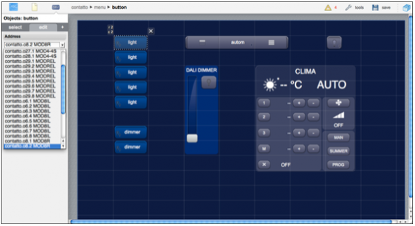
Besides the direct association of control buttons and data points, the CONTATTO driver also automatically updates graphical objects that represent values or states of complex devices, like the CLIMA2 temperature control unit. It will also automatically intercept buttons to manually set operation modes and temperature set-points.
CLIMA2
You can use the temp and tempmini objects to control CLIMA2 devices.
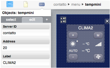
The fan button, in the bottom right-hand corner, is not enabled because the manual control of the fan speed is not available. The M button, in the top right-hand corner, allows to switch the module on or off.
You can also easily create customized controls for the CLIMA2, using standard graphic objects that are automatically set to show the device’s status and intercepted to send user commands.
UISET Actions
| ID | Attribute | Set to | Description |
|---|---|---|---|
| <address>.mode | value | SUMMER | summer mode (cooling) |
| value | WINTER | winter mode (heating) | |
| <address>.mode.label.summer | visible | true | if CLIMA2 is in summer mode |
| <address>.mode.label.winter | visible | true | if CLIMA2 is in winter mode |
| <address>.status | value | OFF | zone off |
| value | ON | zone on | |
| <address>.status.label.off | visible | true | if the zone is not cooling or heating |
| <address>.status.label.cooling | visible | true | if the zone is cooling |
| <address>.status.label.heating | visible | true | if the zone is heating |
| <address>.fan | value | OFF | fan off |
| value | MIN | minimum fan speed | |
| value | MED | medium fan speed | |
| value | MAX | maximum fan speed | |
| <address>.fan.label.min | visible | true | minimum fan speed |
| <address>.fan.label.med | visible | true | medium fan speed |
| <address>.fan.label.max | visible | true | maximum fan speed |
| <address>.setpoint.label.on | visible | true | zone is on |
| <address>.setpoint.label.off | visible | true | zone is off |
| <address>.setpoint.mode | value | ON | zone is on |
| value | OFF | zone is off | |
| <address>.setpoint.temp | value | <value> | the active setpoint temperature, in Celsius degrees with one decimal digit, followed by " °C" |
| <address>.temp | value | <temp> | the measured temperature, in Celsius degrees with one decimal digit, followed by " °C" |
| FAULT | fault/error condition |
USER Commands
| Name | Param | Action |
|---|---|---|
| <address> | on | module on |
| off | module off | |
| mode.summer | set summer mode (cooling) | |
| mode.winter | set winter mode (heating) | |
| <address>.setpoint | temp.up | increase setpoint temperature in 0.5C steps |
| temp.down | decrease setpoint temperature in 0.5C steps | |
| 0...400 | set the setpoint to the defined value (in C/10) | |
| mode | cycle through on and off modes | |
| mode.on | module on | |
| mode.off | module off |
MODCL
You can use the temp and tempmini objects to control MODCL devices.
The fan button, in the bottom right-hand corner, is not enabled because the manual control of the fan speed is not available. The M button, in the top right-hand corner, allows to switch the module to auto or manual mode, or off.
You can also easily create customized controls for the MODCL, using standard graphic objects that are automatically set to show the device’s status and intercepted to send user commands.
UISET Actions
| ID | Attribute | Set to | Description |
|---|---|---|---|
| <address>.mode | value | SUMMER | summer mode (cooling) |
| WINTER | winter mode (heating) | ||
| <address>.mode.label.summer | visible | true | if MODCL is in summer mode |
| <address>.mode.label.winter | visible | true | if MODCL is in winter mode |
| <address>.status | value | OFF | zone off |
| ON | zone on | ||
| <address>.status.label.off | visible | true | if the zone is not cooling or heating |
| <address>.status.label.cooling | visible | true | if the zone is cooling |
| <address>.status.label.heating | visible | true | if the zone is heating |
| <address>.fan | value | OFF | fan off |
| MIN | minimum fan speed | ||
| MED | medium fan speed | ||
| MAX | maximum fan speed | ||
| <address>.fan.label.min | visible | true | minimum fan speed |
| <address>.fan.label.med | visible | true | medium fan speed |
| <address>.fan.label.max | visible | true | maximum fan speed |
| <address>.setpoint | value | 1, 2, 3 | setpoint N is active |
| MAN | manual setpoint is active | ||
| OFF | zone is off | ||
| <address>.setpoint.label.1 | visible | true | setpoint 1 is active |
| <address>.setpoint.label.2 | visible | true | setpoint 3 is active |
| <address>.setpoint.label.3 | visible | true | setpoint 3 is active |
| <address>.setpoint.label.man | visible | true | manual setpoint is active |
| <address>.setpoint.label.off | visible | true | zone is off |
| <address>.setpoint.mode | value | AUTO | automatic mode |
| MAN | manual mode | ||
| OFF | zone is off | ||
| <address>.setpoint.temp | value | <value> | the active setpoint temperature, in Celsius degrees with one decimal digit, followed by " °C" |
| <address>.temp | value | <temp> | the measured temperature, in Celsius degrees with one decimal digit, followed by " °C" |
| FAULT | fault/error condition |
USER Commands
| Name | Param | Action |
|---|---|---|
| <address> | mode | cycle summer/winter modes |
| <address>.mode | mode.summer | set summer mode (cooling) |
| mode.winter | set winter mode (heating) | |
| <address>.setpoint.temp | up | increase current setpoint temperature in 0.5C steps |
| down | decrease current setpoint temperature in 0.5C steps | |
| <address>.setpoint.temp.N | up | increase setpoint N temperature in 0.5C steps |
| down | decrease setpoint N temperature in 0.5C steps | |
| 0...400 | set setpoint N to the given value (in C/10) | |
| <address>.setpoint.temp.man | up | increase manual setpoint temperature in 0.5C steps |
| down | decrease manual setpoint temperature in 0.5C steps | |
| 0...400 | set manual setpoint to the given value (in C/10) | |
| <address>.setpoint | mode | cycle through auto, manual and off modes |
| <address>.setpoint.mode | auto | set auto mode |
| man | set manual mode | |
| off | zone off |
MOD4TP/I
Using slider objects for MOD4TP/I shutter's position
You can use the slider objects, slider|sliderv and slider|sliderh, to display and control the position. Set both the slider's ID and address to <server_name>.<address>.<N>, with N from 1 to 4.
Note that you can set the inverse attribute of the slider|sliderv object to true, in order to have the cursor at the top instead of bottom of the slider when the position is 0.
Release Notes
3.10.0
- MODHT i<address>.fan split into two datapoints, i<address>.fan and i<address>.fan.speed
- new MODHT read/write datapoints: o<address>.pcam.display = <temp | setpoint> and o<address>.options.eco = <0 | 1>
3.9.0
- support of MODAURORA
- support of MODSENSE-CO2
- support of MODSUN
- fixed a bug that, in some specific conditions, could interrupt input and output polling from MODDALI; improved logging in verbose mode
3.8.0
- new option "disablemodhtpulsereset", disables automatic reset of MODHT pulse outputs (panic.reset, dnd.reset, service.reset, fan)
- improved support for MCP firmware upload
- fixes to MODANA and MODANAM: energy data points not updated when energy not changing on all three phases
- fixes to MODPQ5 write commands, that failed when another device on the bus had the same output address of MODPQ5 input address
3.7.0
- support of MODRHT
- support of MODAM2
- support of MODIGLASS, MODIGLASS3
- support of MODLC firmware version 3.2
- support of MODDALI firmware version 6.x
- support of MCP counters
- bus and modules fault detection
- fixes to the MODDALI ballast 1 status data point
3.6.0
- added support for MOD32IL
- added support for MOD4TP/I
- added support for MODDALI8
- added support for MODANAM
- fixed a bug that could cause erroneous readings of MODANA's ptotk datapoint when total active power is negative
3.5.1
- MODANA updated to support negative active energy values (fw. 1.5 or later)
3.5.0
- added support for MCP4
- added support for MODCA firmware version 2.0, with new "relay.forced" datapoint
- added support for MOD32IN
- MODPQ5 is now identified with its unique ID. Use MCPIDE 3.2.3 or later to program the MCPXT/MCP4 to allow HSYCO to correctly identify this module
3.4.0
- improved communication error logging
- improved support of tools remote access
- events generated during startup if startupevents=true are now executed sequentially
- support for MODDI
- support for MODCL
3.2.2
bug fixes:
- the toolspassword optional parameter was incorrectly converted to lower case
- fixed a bug that prevented reading the last 3 addresses of MOAN/I4 and MI420-X4 modules
3.2.1
- added support for MODHT set-point delta limits read and write
- the lux datapoint name was incorrectly set to
ID.i<addr>.1instead ofID.i<addr>.lux
3.2.0
- support for MODCA, MODHT, MODKB, MODPQ5
- new "detectevents" option, generates forced events when a device is detected at start-up
- support for the toolspassword option, to allow MCP-IDE and other tools secure remote access to the MCP via HSYCO
- new clock datapoint to read the MXP-XT internal clock and set it to HSYCO's time
3.0.3
- optimized performance of MCP’s registers status polling
- the server failed to initialized when an unsupported device was configured in the MCP
3.0.1
- you can now limit the number of virtual points and registers read and written by HSYCO, and have access to all of the 1024 registers; defaults are unchanged
3.0.0
- initial release
HSYCO and Home Systems Consulting are registered trademarks of Home Systems Consulting SpA. Java and JavaScript are registered trademarks of Oracle and/or its affiliates. CONTATTO and DUEMMEGI are registered trademarks of DUEMMEGI SRL. Other products or company names can be trademarks or registered trademarks of other companies and are used for demonstrative purposes only, with no violation intent.