MyHome
MyHome is a proprietary bus system for home automation developed by BTicino. HSYCO fully integrates with MyHome using the OpenWebNet (OWN) protocol.
HSYCO supports all MyHome devices and features that the OWN protocol officially supports, including lighting, automation, scenes, AUX and CEN addressing, the temperature control unit and burglar alarm unit.
The bus architecture can be arranged as a single bus or with a riser and several local busses.
Communication
HSYCO supports the Ethernet IP connection to MyHome through IP-based OWN gateways, including the F452, F453, F454, F453AV, F459, MH200, MH200N, MH201 (works in monitor mode only) and MH SERVER 1.
HSYCO also supports the L4686SDK module through an USB connection and an associated virtual serial port.
Gateway Configuration
The OWN gateway must be configured to allow open OWN connections from the IP address assigned to the HSYCO server.
L4686SDK Module
The L4686SDK interface module is connected to HSYCO using a USB cable.
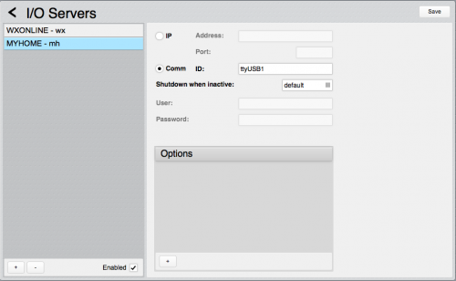
The operating system creates a virtual serial port; its name depends on your HSYCO server configuration, and should be ttyUSB0 if there are no other devices connected to the USB ports.
You could also use the ftdi-n-n.n alias, that is unique for each physical USB port on the server.
For example, in this screenshot we can take a look to the configuration with an L4686SDK connected to the second USB port (ttyUSB1)
L4686SDK Limitations
- L4686SDK firmware version 1.20.0 or later is required
- Not all protocol frames are supported. The I/O server has been tested with the following functions: scenarios, lights, automation, temperature control, AUX and CEN plus
- Check the L4686SDK documentation to know which functions are actually supported, also based on the L4686SDK firmware version
- The clock read and sync functions are not supported
- HSYCO only support the L4686SDK module on a single main bus; private raiser buses are not supported
- the USB connection cable should never be unplugged during normal operations. If the cable is unplugged, HSYCO will not be able to restore the connection to the L4686SDK until it is manually restarted.
HSYCO Configuration
Add a MYHOME I/O Server in the I/O Servers section of the Settingsfield defines the module’s family or function and set its parameters:
Communication
- IP Address: IP address of the gateway. The gateway's MAC address can be used instead of the IP address
- IP Port: TCP/IP port to use, leave blank to use default port 20000.
Authentication
- Password: required when the OpenWebNet gateway requires the HMAC authentication or legacy authentication. (the password can be changed in the System menu of Bticino MyHOME App, it is called "OPEN password")
High Availability
- Shutdown when inactive: defaults to false.
Options
| ID | Default | Values | Description |
|---|---|---|---|
| gui | true | true | enables automatic support of Web GUI objects to show the status of the system and intercept control buttons |
| false | disables support for the Web GUI | ||
| startupevents | false | true | generate IO events also during the driver’s start-up phase |
| false | start generating events only after HSYCO is aligned with the current status of the system | ||
| discovery | true | true | auto-detects MyHome lighting and automation devices that are connected to the bus and are fully operational, and automatically creates the list of all detected devices and individual data points in the systemtopo.txt file |
| false | auto-detect is disabled | ||
| monitoronly | false | true | disable the Command Dispatcher and only use the I/O Server to monitor the bus status (this option is not available with the L4686SDK interface module) |
| false | Command Dispatcher is enabled, and the I/O Server can send commands to the bus | ||
| tempignorelocaloffset | false | true | when sending zones absolute setpoint commands, the local offset is not corrected |
| false | setting a setpoint to an absolute value, it is corrected by the local offset | ||
| tempzones | z<n> | if you want to monitor and control temperature zones, all zone numbers should be listed with the tempzones option. <n> is the zone number. Multiple zones should be separated by semicolons | |
| language | en | en, it, fr | the language used for automatically generated GUI text fields |
| supersocket | true | true | use the "super socket" command session mode |
| false | use the normal command session mode (required for the MH201) | ||
| networkinterface | string | optional local network interface name, used when the gateway's MAC address is used instead of the IP address, and the HSYCO server has more than one network interface |
The 4695 four zone temperature control unit uses a zone address for the control unit itself. This address has to be marked as a special address in the tempzones parameter, enclosing it in round brackets.
For example:
tempZones=(32);33
defines a central unit having address 32, and an additional zone with address 33.
The MyHome I/O Server supports only one central unit for each SCS riser bus.
myhome.ini
The myhome.ini file is a specific configuration file located in the main directory (same directory as hsyco.ini or hsyco.jar).
This file is optional. It is only used to assign friendly names to the burglar alarm zones and technical alarms, so that these names are used in the GUI log and the security.log files.
If you have multiple My Home gateways with multiple burglar alarm panels, the parameters need to be defined for each system, using unique ids, according to the following table:
| ID | Description |
|---|---|
| security.zone.<n> | the friendly name for burglar alarm zone <n> |
| security.aux.<n> | the friendly name for burglar alarm technical alarm <n> |
The myhome.ini is automatically detected at start-up and automatically reloaded whenever it is modified.
For example, the following myhome.ini file is used to define a few friendly names of two distinct My Home systems:
mh1.security.zone.1.name=entrance
mh1.security.zone.2.name=lobby
mh1.security.aux.1.name=flooding
mh2.security.zone.3.name=windows
mh2.security.zone.5.name=driveway
The Device Configuration Database
The systemtopo.txt file contains the list of all lighting and automation devices that could be directly associated to graphic object in the Web-based user interface.
This file can be filled manually or automatically by HSYCO at start-up. To enable automatic discovery and automatic generation of devices’ information in the systemtopo file, use the discovery option in System Settings. The discovery feature is enabled by default.
This is an example of an automatically generated systemtopo.txt file:
(devices)
mh.autom.82 : AUTOM ; VSHUT ;
mh.autom.88 : AUTOM ; VSHUT ;
mh.autom.93 : AUTOM ; VSHUT ;
mh.autom.96 : AUTOM ; VSHUT ;
mh.light.11 : LIGHT ; LIGHT ;
mh.light.12 : LIGHT ; LIGHT ;
mh.light.13 : LIGHT ; LIGHT ;
mh.light.16 : LIGHT ; LIGHT ;
mh.light.25 : LIGHT ; DIMMER ; DIMMER
Note that HSYCO can automatically detects dimmer modules if they are on when discovery is performed. If a dimmer is off, it will be listed as an ordinary on/off light module, and should be manually changed to DIMMER.
You should manually add comments and other optional parameters:
(devices)
mh.autom.82 : AUTOM ; VSHUT ; driveway gate
mh.autom.88 : AUTOM ; VSHUT ; awning
mh.autom.93 : AUTOM ; VSHUT ; kitchen shutter
mh.autom.96 : AUTOM ; VSHUT ; bedroom shutter
Also, if you want to use (button) objects in the Project Editor to control scenes, you should manually add scenes definitions in systemtopo.txt, as HSYCO can’t automatically detect scene modules and stored scenes:
(devices)
mh.scene.94.5 : LIGHT ; SCENE ; close all shutters
mh.scene.94.10 : LIGHT ; SCENE ; night mode
Datapoints
The naming convention HSYCO uses for the events and to control all MyHome devices is closely related to the MyHome addressing standards and the OpenWebNet protocol implementation.
In OWN, the standard monitor and command frames have the following format:
*<who>*<what>*<where>##
The <who> field defines the module’s family or function. <what> is the state of a device, for example 0 for off and 1 for the on state of an on/off module. Finally, <where> is the module’s address, including the local bus number if the module is not on the riser bus.
With few exceptions, this frame format translates to the following event format inside HSYCO:
IO servername.<who>.<where> = <what>
The WHO field in OWN frames is a number, while we use a literal string in HSYCO to make names easier to read.
The table below lists all supported <who> functions and the HSYCO’s corresponding literals that form the prefix of all IO data points.
| OWN WHO | HSYCO Prefix | Function Description |
|---|---|---|
| 0 | scene | scenario module |
| 1 | light | lighting module |
| 2 | autom | automation module (inter-locking) |
| 3 | load | load control |
| 4 | temp | temperature control |
| 5 | security | burglar alarm panel |
| 9 | aux | auxiliary address |
| 15 | cen | cen modules / addresses |
| 25 | cenplus | cen plus modules and dry contacts / IR modules |
The <where> field in OWN is, in most cases, the numeric address of a module, eventually followed by #4#<b> for modules on local buses (<b>< is the local bus numerical id). Group addressing has the <where> field formatted as #<g>, where <g> is the group’s numerical id.
The table below defines the conversion rules between the OWN <where> format and HSYCO’s data points format.
| OWN WHERE | HSYCO Format | Description |
|---|---|---|
| <n> | <n> | if <n> is a plain number, it is used as-is in HSYCO. Note that you should retain the leading zero when present. 01 is not equivalent to 1 in OWN, and HSYCO simply passes the where field back and forth with no changes |
| #<n> | g<n> | group addresses are represented in HSYCO as a lowercase g followed by the group numerical id, from 1 to 9 |
| <n>#4#<b> | l<b>.<n> | a lowercase l and the local bus id are prefixed to the base address |
| #<n>#4#<b> | l<b>.g<n> | group addressing on local buses |
The <what> field represents the value or action, and corresponds to the data point value in HSYCO. Each function supports a specific set of <what> values.
Gateway Module
| ID | Value | R/W | Description |
|---|---|---|---|
| connection | online | R | connection established to the OWN gateway |
| offline | R | HSYCO can’t connect to the OWN gateway | |
| frame | OWN raw frame | R | a frame event is generated on incoming frames, based on the monitor setting (see below) |
| W | send a raw OWN frame to the gateway | ||
| monitor | none | W | the frame datapoint is not set with monitored frames |
| ignored | W | the frame datapoint is set with monitored frames that are not recognized and translated to specific events | |
| all | W | the frame datapoint is set with any monitored frame | |
| clock | sync | W | set the gateway clock to HSYCO’s current time |
| read | W | read the gateway clock, and the delta with HSYCO’s time | |
| <yyyy>-<mm>-<dd> <hh>:<mm>:<ss> | R | the gateway clock current time | |
| clock.delta | integer | R | the delta time in seconds between the gateway and HSYCO clocks. A positive number means that the gateway clock is ahead of HSYCO |
Scenario Modules
| ID | Value | R/W | Description |
|---|---|---|---|
| scene.<module> scene.<bus>.<module> | erase | R | all scenarios erased |
| W | erase all scenarios | ||
| lock | R | module is locked (cannot erase or record scenarios) | |
| W | lock the scenario module | ||
| unlock | R | module is unlocked (can erase and record scenarios) | |
| W | unlock the scenario module | ||
| unavailable | R | the scenario module is busy | |
| full | R | the scenario module memory is full | |
| scene.<module>.<scene> scene.<bus>.<module>.<scene> | 1 | R | scenario activated |
| W | execute scenario | ||
| on | W | execute scenario | |
| 0 | R | scenario deactivated or cleared | |
| W | deactivate scenario | ||
| off | W | deactivate scenario | |
| clear | W | clear scenario status, without sending the deactivate command to the module | |
| record | R | recording | |
| W | start recording | ||
| end | R | end of recording | |
| W | stop recording | ||
| erase | R | the scenario has been erased | |
| W | erase scenario |
<module> is the scenario module address, from 01 to 99 (retain the leading 0).
<bus> is the local bus ID, from 1 to 9, when the scenario module is on a local bus and not on the riser bus.
<scene> is the scenario number, from 1 to 32 (do not add a leading 0 for numbers less than 10).
The unavailable event is generated when the scenario module cannot accept commands. This usually happens when the module is recording a scenario and at the same time is asked to execute another scenario.
Lighting: on/off Modules
| ID | Value | R/W | Description |
|---|---|---|---|
| light.<where> | 1 | R | on status |
| W | turn on | ||
| on | W | turn on | |
| 0 | R | off status | |
| W | turn off | ||
| off | W | turn off | |
| lock | W | lock (disable) | |
| unlock | W | unlock (enable) |
When a module is locked, it doesn’t respond to any bus command except the unlock command.
Lighting: Dimmer Modules
| ID | Value | R/W | Description |
|---|---|---|---|
| light.<where> | 1 | W | turn on at last level |
| on | W | turn on at last level | |
| 0 | R | off status | |
| W | turn off | ||
| off | W | turn off | |
| <x>% | R | <x>% level | |
| W | set to <x>% level | ||
| <x> | W | set to <x>% level | |
| <x>/<y> | W | set to <x>/<y> level | |
| fault | R | load fault detected | |
| lock | W | lock (disable) | |
| unlock | W | unlock (enable) |
Dimmers level can be set between 20% and 100%, in 10% steps.
Automation: Inter-locking Modules
| ID | Value | R/W | Description |
|---|---|---|---|
| autom.<where> | unknown | R | the module’s status is unknown at this time |
| offup | R | off in up position | |
| offdown | R | off in down position | |
| stop off 0 | W | stop | |
| up | R | going up | |
| W | up/open command | ||
| down | R | going down | |
| W | down/close command | ||
| lock | W | lock (disable) | |
| unlock | W | unlock (enable) |
When the MyHome driver starts, and until an up or down command is sent to the module, HSYCO sets the data point value to unknown.
The offup and offdown status values do not represent the fully up/opened or down/closed position of the mechanical device controlled by the module, but just the fact that the module was commanding an up or down movement before being stopped.
Temperature Control: Central Unit
| ID | Value | R/W | Description |
|---|---|---|---|
| temp.control | 0 | R | supervisor control of central unit disabled |
| 1 | R | supervisor control of central unit enabled | |
| temp.zone.off [forced event] | 1 | R | at least one zone is set to off mode |
| temp.zone.protection [forced event] | 1 | R | at least one zone is set to protection mode |
| temp.zone.manual [forced event] | 1 | R | at least one zone is set to manual mode |
| temp.fault [forced event] | 1 | R | generic fault |
| temp.battery.fault [forced event] | 1 | R | central unit battery fault |
| temp.mode | winter | R | winter mode |
| W | set winter mode | ||
| summer | R | summer mode | |
| W | set summer mode | ||
| temp.setpoint | off | R | off mode |
| protection | R | temperature protection mode | |
| <t> | R | when setpoint.mode=man, <t> is the temperature setpoint in °C/10 | |
| <p> | R | when setpoint.mode=auto, <p> is the weekly program, from 1 to 3 | |
| <s> | R | when setpoint.mode=scenario, <s> is the scenario number, from 1 to 16 | |
| <d> | R | when setpoint.mode=away, <d> is the number of days, from 1 to 255 | |
| <p> | R | when setpoint.mode=holiday, <p> is the weekly program to be set at the end of the day | |
| temp.setpoint.mode | off | R | central unit is off |
| protection | R | central unit is in temperature protection mode | |
| man | R | central unit is in manual mode | |
| auto | R | central unit is in automatic mode | |
| scenario | R | central unit is in scenario mode | |
| away | R | central unit is in away mode | |
| holiday | R | central unit is in holiday mode | |
| temp.command | off | W | turn the system off |
| protection | W | set temperature protection mode | |
| 1 | W | set weekly program 1 | |
| 2 | W | set weekly program 2 | |
| 3 | W | set weekly program 3 | |
| <t> | W | set to manual mode, temperature <t> (in C/10), for example t=215 is 21.5 °C | |
| up | W | set to manual mode, raising the setpoint by 0.5 °C | |
| down | W | set to manual mode, lowering the setpoint by 0.5 °C | |
| holiday | W | set holiday program (returns to weekly program 1 at midnight) | |
| holiday.<n> | W | set holiday program (returns to weekly program <n> at midnight) | |
| away.<yyyymmdd> | W | set away mode until the day passed as parameter, returning to weekly program 1 at midnight | |
| away.<yyyymmdd> .<n> | W | set away mode until the day passed as parameter, returning to weekly program <n> at midnight | |
| away.<d> | W | set away mode for <d> days, returning to weekly program 1 at midnight | |
| away.+<d> | W | increases the number of away days by <d>, starting from 2 days | |
| away.-<d> | W | decreases the number of away days by <d> | |
| away.<d>.<n> | W | set away mode for <d> days, returning to weekly program <n> at midnight | |
| scenario.<n> | W | set scenario mode <n> |
Temperature Control: Zones
In the following table, <z> is the zone number, from 1 to 99.
| ID | Value | R/W | Description |
|---|---|---|---|
| temp.<z>.cooling.status | 0 | R | zone actuator off in summer mode |
| 1 | R | zone actuator on in summer mod | |
| temp.<z>.fan | off | R | fan is off |
| min | R | slow fan speed | |
| med | R | medium fan speed | |
| max | R | fast fan speed | |
| temp.<z>.mode | winter | R | winter mode |
| summer | R | summer mode | |
| temp.<z>.setpoint | off | W | turn zone off |
| auto | W | set zone to automatic mode | |
| protection | W | set zone to temperature protection mode | |
| up | W | set zone to manual mode, raising the setpoint by 0.5 °C | |
| down | W | set zone to manual mode, lowering the setpoint by 0.5 °C | |
| <t> | R | current temperature setpoint <t> (in °C/10), corrected with local offset | |
| <t> | R | set zone to manual mode, temperature <t> (in °C/10), for example t=215 is 21.5 °C | |
| temp.<t>.setpoint.local | -3 ... +3 | R | zone local offset is set to -3 ... +3 |
| protection | R | zone locally set to protection mode | |
| off | R | zone locally set to off | |
| temp.<z>.setpoint.mode | off | R | zone is off |
| auto | R | automatic mode | |
| man | R | manual mode | |
| protection | R | protection mode | |
| temp.<z> | unlock | W | zone unlock |
Burglar Alarm: Main Panel
| ID | Value | R/W | Description |
|---|---|---|---|
| security.active | 0 | R | the burglar alarm panel is not active |
| 1 | R | the burglar alarm panel is active (not necessarily armed) | |
| security.alarm | 0 | R | no alarm |
| 1 | R | ongoing alarm condition | |
| security.delay [forced event] | end | R | end of arming delay (system now fully armed) |
| security.lowbattery | 0 | R | battery ok |
| 1 | R | low battery or battery fault condition | |
| security.maintenance | 0 | R | not in maintenance mode |
| 1 | R | maintenance mode | |
| security.nopower | 0 | R | AC power ok |
| 1 | R | fault condition on the AC power supply | |
| security.programming | 0 | R | not in programming mode |
| 1 | R | programming mode | |
| security.status | off | R | system not armed |
| armed | R | system armed |
Note that, because the MyHome burglar alarm panel cannot be directly controlled via OpenWebNet commands, there are no write-enabled data points for this system.
Burglar Alarm: Zones and Technical (aux)
In the following table, <z> is the zone number.
| ID | Value | R/W | Description |
|---|---|---|---|
| security.aux.<z>.alarm [forced event] | 0 | R | technical alarm reset |
| 1 | R | technical alarm zone <z> | |
| security.sensor.<z>.fault [forced event] | 1 | R | sensor <z> fault |
| security.zone.<z>.active | 0 | R | zone <z> is not active |
| 1 | R | zone <z> is active | |
| security.zone.<z>.alarm | 0 | R | zone <z> intrusion alarm reset |
| 1 | R | zone <z> intrusion alarm | |
| security.zone.<z>.panic | 0 | R | zone <z> panic alarm reset |
| 1 | R | zone <z> panic alarm | |
| security.zone.<z>.tamper | 0 | R | zone <z> tamper alarm reset |
| 1 | R | zone <z> tamper alarm |
Auxiliary Addresses
| ID | Value | R/W | Description |
|---|---|---|---|
| aux.<where> | 1 | R | on status |
| W | turn on | ||
| on | W | turn on | |
| 0 | R | off status | |
| W | turn off | ||
| off | W | turn off |
CEN Modules
| ID | Value | R/W | Description |
|---|---|---|---|
| cen.<where>.<bt> | on | R | button <bt> (00-31) pressed |
| W | virtual press of button <bt> | ||
| off | R | button <bt> (00-31) released after short time (<= 0.5s) | |
| W | virtual short time release of button <bt> | ||
| offlong | R | button <bt> (00-31) released after long time (> 0.5s) | |
| W | virtual long time release of button <bt> | ||
| onrepeat | R | button <bt> (00-31) continues to be pressed (this event repeats every 0.5s) | |
| W | virtual long time pressure of button <bt> |
CENPLUS Modules
| ID | Value | R/W | Description |
|---|---|---|---|
| cenplus.<where>.<bt> (used for CEN PLUS command modules) | on | R | button <bt> (00-31) pressed |
| W | virtual press of button <bt> | ||
| off | R | button <bt> (00-31) released after short time (<= 0.5s) | |
| W | virtual short time release of button <bt> | ||
| offlong | R | button <bt> (00-31) released after long time (> 0.5s) | |
| W | virtual long time release of button<bt> | ||
| onrepeat | R | button <bt> (00-31) continues to be pressed (this event repeats every 0.5s) | |
| W | virtual long time pressure of button <bt> | ||
| cenplus.<where> (used for DRY CONTACT and IR modules) | on | R | on status |
| W | turn on | ||
| off | R | off status | |
| W | turn off | ||
| request | W | request a status update |
The <where> field used for command modules is prefixed by the 2 character in front of the address, while dry contact and IR modules have the <where> field prefixed with 3.
| WHERE | Value | Description |
|---|---|---|
| 2 | 0-2047 | CEN PLUS modules configured with Advanced Virtual Configuration |
| 3 | 1-201 | for automation dry contact interface (3477 and F428) <where> should be configured using the Virtual Configurator Software |
| 3 | [1-9][1-9] | for alarm dry contact interface and IR (3480, F482, IR 4610, 4611, 4640) <where> is configured using <z> and <n> with physical configuration pins |
F421 Load Control Unit
| ID | Value | R/W | Description |
|---|---|---|---|
| load.voltage | refresh | W | requests the measured voltage |
| V | R | measured voltage, in Volts | |
| load.current | refresh | W | requests the measured current |
| I | R | measured current, in Amperes | |
| load.power | refresh | W | requests the measured power |
| P | R | measured power, in Watts | |
| load.energy | refresh | W | requests the measured energy |
| E | R | measured energy |
Note that reading a measured value to the F421 load control unit requires a relatively long time (up to about 4 seconds, based on our tests) and, during this time, the My Home gateway is unable to process any other request. This can result in temporary slowdown of the execution of other commands.
User Interface
Temperature Control Unit
UISET Actions
| ID | Attribute | |
|---|---|---|
| temp.status | value | summer/winter followed by the current status, for example: WINTER MAN 21.0 °C |
USER Commands
| Name | Param | Action |
|---|---|---|
| temp.command | off | turn the system off |
| temp.command | protection | set temperature protection mode |
| temp.command | 1 | set weekly program 1 |
| temp.command | 2 | set weekly program 2 |
| temp.command | 3 | set weekly program 3 |
| temp.command | <t> | set to manual mode, temperature <t> (in °C/10), for example t=215 is 21.5 °C |
| temp.command | up | set to manual mode, raising the setpoint by 0.5 °C |
| temp.command | down | set to manual mode, lowering the setpoint by 0.5 °C |
| temp.command | holiday | set holiday program (returns to weekly program 1 at midnight) |
| temp.command | holiday.<n> | set holiday program (returns to weekly program <n> at midnight) |
| temp.command | away.<yyyymmdd> | set away mode until the day passed as parameter, returning to weekly program 1 at midnight |
| temp.command | away.<yyyymmdd>.<n> | set away mode until the day passed as parameter, returning to weekly program <n> at midnight |
| temp.command | away.<d> | set away mode for D days, returning to weekly program 1 at midnight |
| temp.command | away.+<d> | increases the number of away days by <d>, starting from 2 days |
| temp.command | away.-<d> | decreases the number of away days by <d> |
| temp.command | away.<d>.<n> | set away mode for <d> days, returning to weekly program <n> at midnight |
| temp.command | scenario.<n> | set scenario mode <n> |
Temperature Zones
The standard TempMini object can be used to control each zone. The fan speed indicator is not visible if the zone is not configured for fan control.
Set the I/O server id in the Server ID field, and temp.<z> where <z> is the zone number from 1 to 99 in the Address field.
The Temp object is not supported for the MyHome system.
Zone unlock
If a zone has been locked in the off or protection modes using the local dial, you can create a [[User]] object to unlock that zone.
| Name | Param | Action |
|---|---|---|
| temp.<z> | unlock | unlock zone <z> |
Burglar Alarm Unit
UISET Actions
| ID | Attribute | |
|---|---|---|
| security.status | value | shows system status: ARMED, DISARMED or MAINTENANCE |
| security.alarm | value | shows ALARM if there is an ongoing alarm condition, empty otherwise |
| security.alarm.type | value | shows the alarm type, if not an intrusion alarm: TAMPER, PANIC or TECHNICAL |
| security.zones | value | shows zones 1-8 activation status, for example: 12-----8 means that only zones 1, 2 and 8 are active |
| security.log.<n> | value | log line <n> of the events log, where <n> is between 1 and 20. Line 1 lists the most recent event |
| security.status.label.maintenance | visible | true only when the burglar alarm panel is in maintenance mode |
| security.status.label.active | visible | true only when the burglar alarm panel is active (not necessarily armed) |
| security.lowbattery.label | visible | true only when there is a low battery or battery fault condition |
| security.acfault.label | visible | true only when there is a fault condition on the AC power supply |
| security.status.label.armed | visible | true only when the system is armed |
| security.alarm.label.intrusion | visible | true only when there is an ongoing intrusion alarm condition |
| security.alarm.label.tamper | visible | true only when there is an ongoing tamper alarm condition |
| security.alarm.label.panic | visible | true only when there is an ongoing panic alarm condition |
| security.alarm.label.aux | visible | true only when there is an ongoing technical alarm condition |
USER Commands
Because the MyHome burglar alarm panel cannot be directly controlled via OpenWebNet commands, there are no standard control objects for this system.
Release Notes
3.8.0
- added support for legacy OpenWebNet password authentication
- the OpenWebNet gateway can also be addressed using its MAC address
3.7.0
- added support for HMAC authentication (for MyHome Server 1 and other recent OpenWebNet gateways)
3.6.0
- new "tempignorelocaloffset" option: when true, when sending zones absolute setpoint commands, the local offset is not corrected. Defaults to false
3.5.1
- new "monitoronly" option. Set to true to disable the Command Dispatcher and only use the I/O Server to monitor the bus status. Defaults to false
3.4.0
- bug-fix: when using the L4686SDK interface, added a small delay when sending commands, to ensure that feedback is properly received by the L4686SDK
3.3.0
- added support of the L4686SDK interface module
3.2.2
- clock read and sync are now based on local time
3.2.1
- improved handling of connection errors
3.2.0
- new clock datapoint to read the gateway’s internal clock and set it to HSYCO's time
3.0.0
- initial release
MyHome and BTicino are registered trademarks of BTicino SpA.