Domino
The DOMINO system is DUEMMEGI’s proprietary bus architecture for home automation. HSYCO fully integrates with this system through the DFCP or DFCP4 control and gateway module, and its FXP-XT serial communication protocol.
A serial connection between the DFCP and the HSYCO SERVER is required for the integration, either directly through the server’s RS-232 port or via the RS-232 port of a supported serial to IP gateway, including the WEBS module.
The DFCP4 can be connected via the integrated serial to IP gateway.
The Domino I/O Server requires DFCP firmware version 2.0 or later for normal operation. Firmware version 4.3 or later is required to support field upgrade of installed Domino modules. The DCPIDE configuration tools pass-through support for secure access to the DFCP via HSYCO requires DCPIDE version 3.2.1 or later.
Communication
Employ a DE-9 (often called DB-9) male-female RS-232 straight cable to connect the RS-232 DFCP port to the serial port on HSYCO SERVER or serial gateway.
RS-232 parameters:
| Baud rate | 9600, 38400, 57600 or 115200 bps (according to the DFCP serial port setting) |
| Data bits | 8 |
| Stop bit | 1 |
| Parity | none |
| Flow control | none |
A speed of 115200 bps is recommended to achieve good performance, particularly when the number of devices connected to the bus is large.
High Availability
- Shutdown when inactive: defaults to false.
HSYCO Configuration
You can define and connect to more than one DOMINO bus using several DFCP gateways.
The DOMINO I/O Server also supports dual, redundant connections between HSYCO and DFCP.
If the main connection fails, HSYCO automatically re-routes the communication with DFCP through the fail-over connection.
Options
| ID | Default | Values | Description |
|---|---|---|---|
| startupevents | false | true | generate IO events also during the driver’s start-up phase |
| false | start generating events only after HSYCO is aligned with the current status of the system | ||
| inputdiscovery | false | true | auto-detects DOMINO’s input devices as configured in the DFCP, and automatically creates the list of all detected devices and individual data points in the systemtopo.txt file. Should be enabled to allow the automatic update of (button) objects’ states |
| false | auto-detect for input devices is disabled | ||
| outputdiscovery | true | true | auto-detects DOMINO’s output devices as configured in the DFCP, and automatically creates the list of all detected devices and individual data points in the systemtopo.txt file. Should be enabled to allow the automatic update of (button) objects’ states |
| false | auto-detect for output devices is disabled | ||
| virtualdiscovery | false | true | auto-detects DOMINO’s virtual points for input and output devices as configured in the DFCP, and automatically creates the list of all detected virtual data points in the systemtopo.txt file. Should be enabled to allow the automatic update of (button) objects’ states |
| false | auto-detect for devices’ virtual data points is disabled | ||
| virtualpoints | false | 1...2033 | enables polling for the first n virtual points of the DFCP. Enable this option only if you need to generate I/O events based on these virtual points |
| true | enables polling for all the 2032 virtual points of the DFCP | ||
| false | polling of the DFCP virtual data points is disabled | ||
| registers | false | 1...1024 | enables polling for registers R0-Rn of the DFCP. Enable this option only if you need to generate I/O events based on these registers |
| true | enables polling for registers R0-R127 of the DFCP | ||
| false | polling of the DFCP registers is disabled | ||
| powerdisplay | false | true | enables polling for registers R0-Rn of the DFCP. Enable this option only if you need to generate I/O events based on these registers |
| ≥ 0 (DFANA address) | enables the automatic display in the GUI of the total real power measured by a DFANA module connected to this DFCP. Note that, if you have more than one DFCP gateway, you should enable this option for one gateway only | ||
| false | power display disabled for this DFCP | ||
| powersensivity | 50 | ≥ 0 | measured power changes are reported only if the difference from last reading is equal or greater than the power sensivity option, in Watts |
| powerinterval | 1 | ≥ 0 | power polling interval for the DFCC meter, in seconds |
| detectevents | false | true | generate forced events when a device is detected at start-up |
| false | do not generate events when a device is detected at start-up | ||
| toolspassword | string | set this option with a long string (only letters and numbers) password to allow the remote connection of DFCP-IDE and other configuration tools to the DFCP gateways that are connected to HSYCO. For additional security, it is recommended to set this option only when required | |
| language | english | en it fr | language for all messages from the DOMINO system: English, Italian or French |
Initialization and Connection Events
| Event name | Value | Description |
|---|---|---|
| connection | online | connection established to the DFCP module |
| offline | HSYCO can’t connect to the DFCP module | |
| detected.input.<n>.<s> | model name | an input device of the type passed as value has been detected at address <n>, using <s> addresses |
| detected.output.<n>.<s> | model name | an output device of the type passed as value has been detected at address <n>, using <s> addresses |
The Device Configuration Database
The systemtopo.txt file contains the list of all devices and their individual input, output and virtual data points that could be directly associated to graphic object in the Web-based user interface. This file can be filled manually or automatically by HSYCO at start-up. To enable automatic discovery and automatic generation of devices’ information in the systemtopo file, use the inputdiscovery, outputdiscovery and virtualdiscovery options in Settings. The default behavior is to only discover devices with output data points.
This is an example of an automatically generated systemtopo.txt file:
(devices)
domino.o10.1 : LIGHT ; LIGHT
domino.o6.1 : LIGHT ; DIMMER
domino.o7.2 : LIGHT ; LIGHT
domino.o7.1 : LIGHT ; DIMMER
domino.o9.2 : AUTOM ; VSHUT
domino.o5.4 : LIGHT ; LIGHT
domino.o9.1 : AUTOM ; VSHUT
domino.o5.3 : LIGHT ; LIGHT
domino.o5.2 : LIGHT ; LIGHT
domino.o5.1 : LIGHT ; LIGHT
You should then manually add comments and other optional parameters:
(devices)
domino.o10.1 : LIGHT ; LIGHT; main entrance light
domino.o6.1 : LIGHT ; DIMMER; lobby dimmer
domino.o7.2 : LIGHT ; LIGHT; kitchen workbench
domino.o7.1 : LIGHT ; DIMMER; kitchen main dimmer
DFCP Data Points
The DFCP implements 2032 virtual points for binary (on/off) data and 1024 registers and counters for positive scalar values (0-65535). The DFH doesn't support virtual points or registers.
All virtual points, registers and counters can optionally generate I/O events. You can also write to the virtual data points, registers or counters using the IO action in EVENTS or ioSet() method in Java.
You cannot directly control the DFCP virtual data points, registers or counters using GUI objects.
To enable polling of the current state of the DFCP’s virtual data points, enable the virtualpoints options in hsyco.ini.
To enable polling of the current state of the DFCP’s registers, enable the registers options in hsyco.ini.
To enable polling of the current state of the DFCP’s counters, enable the counters options in hsyco.ini.
If you only have to write to virtual points or registers, enabling polling is not strictly required.
| ID | Value | R/W | Description |
|---|---|---|---|
| busfault | 0 | R | no bus fault detected |
| 1 | R | bus fault detected | |
| modulefault | 0 | R | no modules fault detected |
| 1 | R | modules fault detected | |
| v0.<n> | 0 | RW | virtual data point <n> off (<n>: 1-2032) |
| 1 | RW | virtual data point <n> on (<n>: 1-2032) | |
| r0.<n> | <x> | RW | register <n> (<n>: 0-1023) set to value <x> (<x>: 0-65535) |
| c0.<n> | <x> | RW | counter <n> (<n>: 0-1023) set to value <x> (<x>: 0-65535) |
| devicecommlog | off | W | disable all FXP-XT traffic log |
| i<address> or o<address> | W | enables FXP-XT traffic log of polling and commands sent to an input or output device. Always use the base address of the device. Writing to this datapoint multiple times, after log has started, allows to log traffic of multiple devices |
DFCP Internal Clock
The DFCP module has an integrated real-time clock. You can use the clock datapoint to read the DFCP date and time, and set the DFCP clock to HSYCO’s current time.
| ID | Value | R/W | Description |
|---|---|---|---|
| clock | yyyy-mm-dd hh:mm:ss | R | the DFCP clock current time |
| read | W | read the DFCP clock, and the delta with HSYCO’s time | |
| sync | W | set the DFCP clock to HSYCO’s current time | |
| clock.delta | integer number | R | the delta time in seconds between the DFCP and HSYCO clocks. A positive number means that the DFCP clock is ahead of HSYCO |
DFH redundant configuration for High Availability applications
When HSYCO is embedded in a DFH interface, high availability support can be configured to allow two DFH to be connected to the same Domino bus. In normal operations, the master unit will be active on the bus, while the slave unit will automatically block bus polling, to avoid traffic conflicts with the master unit.
DFH high availability support requires DFH firmware version 3.3 or above.
If the slave HSYCO becomes active, because it automatically detects a master's failure, the Domino I/O server will exit its idle state, and the slave DFH interface will resume polling the bus. The time required by the slave to take over the active role and become the bus master depends on the haTimeoutSeconds configuration parameter; its default is 4 seconds. A few seconds of bus polling overlapping are also normal when the master becomes active again.
In a typical configuration, the following high availability parameters should be set like:
haClientSessionsFailover = true
haDisableCommandEvents = true
haDisableFilesSync = false
haTimeoutSeconds = 4
Also, the ioServersShutdownInactive parameter of the Domino I/O server, on both master and slave, should be false (or default).
Without additional configuration, this setup will correctly address a total failure of the master DFH unit, but not other fault conditions, like a bus fault on the master unit, or LAN fault on the master or slave DFH.
If a bus fault occurs on the master DFH, HSYCO would still be active and the slave remains idle, as it would still sense the master's presence over the LAN. Also, if the master becomes disconnected from the LAN, it would still remain active, but the slave would also become active, causing polling conflicts on the Domino bus. To address these specific failure modes, add the following lines, or something similar, to the EVENTS file:
$HAMASTER$ = 1 and (IO domino.busfault = "1" or IO system.internet.connection = "offline") : { haActive(false); }
$HAMASTER$ = 1 and (IO domino.busfault = "0" and IO system.internet.connection = "online") : { haActive(true); }
The first rule forces the master to relinquish its active state in case of bus failure or when the internet connection is lost. You should probably replace the internet connection test with an equivalent command that tests local services on your LAN.
The second rule reacquires the master's active state when both the Domino bus and the LAN connections are up.
Another fault scenario that should be considered is the loss of LAN access from the slave DFH. In this case the master would remain active, but the slave HSYCO would also become active, not sensing the master. This should again be prevented, to avoid polling conflicts, with the following rules in EVENTS:
$HAMASTER$ = 0 and IO system.internet.connection = "offline" : { ioServersStop("domino"); }
$HAMASTER$ = 0 and IO system.internet.connection = "online" : { ioServersRestart("domino"); }
These rules will stop the Domino I/O server when the slave LAN is down, effectively blocking the slave DFH polling, and restart it when up.
Note that there could be other specific fault scenarios to be considered. The example presented here is only one of several possible ways to implement a DFH-based high availability configuration, and may not be adequate to handle all possible fault scenarios in an actual installation.
DOMINO Modules Events and Control
Each DOMINO module has its own set of read-only or read-write data points, mapping the specific set of features.
All modules also have a read-only "fault" data point, set to 1 if the DFCP has detected a module fault condition, or 0 if the module is working normally.
| ID | Value | R/W | Description |
|---|---|---|---|
| i<address>.fault | 0 | R | input module working normally |
| 1 | R | input module fault detected | |
| o<address>.fault | 0 | R | output module working normally |
| 1 | R | output module fault detected |
| Module Code | Description |
|---|---|
| DF4I | 4 digital inputs |
| DFCK3 | clock |
| DF8I | 2x4 digital inputs |
| DF2R | 2 outputs (relay) |
| DF4R, DF4RP | 4 outputs (power relay) |
| DF4RP/I | 4 generic inputs ON-OFF + 4 outputs |
| DF4RI / DF4RIR | multifunction module with 4 digital inputs and 4 outputs (power relay) |
| DF8RIT | multifunction module with 8 digital inputs, 8 outputs (power relay), 1 temperature sensor/controller |
| DFDI, DFDI2, DFDI2B, DFDM, DFDT | 1 output (dimmer) |
| DFDMX | DMX interface |
| DFDALI | DALI interface |
| DFDALI64 | DALI interface |
| DFDV | 1 output (1-10V - ballast) + 1 output (power relay) |
| DF4DV | 4 outputs (1-10V - ballast) |
| DFPID | 1 output (0-10V) + 2 outputs (power relay) |
| DFTP | 2 outputs (shutters) |
| DFTP/I | 2 outputs (shutters) + 4 digital inputs |
| DFTR | 2 outputs (shutters) + 1 output (relay) |
| DF4IL | 4 digital inputs + 4 outputs (LED) |
| DF8IL | 8 digital inputs + 8 outputs (LED) |
| DFIGLASS | 6 button touch keypad with optional temperature sensor |
| AURORA | 6 button touch keypad with optional temperature and humidity sensor |
| DFAI | 2 analog inputs |
| DFAM2 | 2 analog inputs |
| DFLS / DFLS-P | ambient light sensor and presence detector |
| DFLUX, DFSUN | light sensor |
| DFCT/DFTZ/DFTZ2 | temperature sensor |
| DFMB-C | Modbus control interface for HVAC units |
| DFRHT | temperature and humidity sensor |
| DFMETEO | weather module |
| DFANA | electric energy network analyser |
| DFANA-M | electric energy network analyser |
| DFANA-M/CC | electric energy meter and load manager |
| DFCC | electric energy meter and load manager |
| DFCC2 | electric energy meter and load manager |
| DFTA / DFTE | temperature sensor module |
DF4I
The DF4I is an input module with 4 digital inputs.
It uses one address in the DOMINO bus.
| ID | Value | R/W | Description |
|---|---|---|---|
| i<address>.1 | 0 | R | input pin 1 off |
| 1 | R | input pin 1 on | |
| i<address>.2 | 0 | R | input pin 2 off |
| 1 | R | input pin 2 on | |
| i<address>.3 | 0 | R | input pin 3 off |
| 1 | R | input pin 3 on | |
| i<address>.4 | 0 | R | input pin 4 off |
| 1 | R | input pin 4 on |
DFCK3
The DFCK3 is an input module for managing up to 15 different zones with an integrated clock.
It uses one address in the DOMINO bus.
| ID | Value | R/W | Description |
|---|---|---|---|
| i<address>.1 | 0 | R | input pin 1 off |
| 1 | R | input pin 1 on | |
| i<address>.2 | 0 | R | input pin 2 off |
| 1 | R | input pin 2 on | |
| i<address>.3 | 0 | R | input pin 3 off |
| 1 | R | input pin 3 on | |
| i<address>.4 | 0 | R | input pin 4 off |
| 1 | R | input pin 4 on | |
| i<address>.5 | 0 | R | input pin 5 off |
| 1 | R | input pin 5 on | |
| i<address>.6 | 0 | R | input pin 6 off |
| 1 | R | input pin 6 on | |
| i<address>.7 | 0 | R | input pin 7 off |
| 1 | R | input pin 7 on | |
| i<address>.8 | 0 | R | input pin 8 off |
| 1 | R | input pin 8 on | |
| i<address>.9 | 0 | R | input pin 9 off |
| 1 | R | input pin 9 on | |
| i<address>.10 | 0 | R | input pin 10 off |
| 1 | R | input pin 10 on | |
| i<address>.11 | 0 | R | input pin 11 off |
| 1 | R | input pin 11 on | |
| i<address>.12 | 0 | R | input pin 12 off |
| 1 | R | input pin 12 on | |
| i<address>.13 | 0 | R | input pin 13 off |
| 1 | R | input pin 13 on | |
| i<address>.14 | 0 | R | input pin 14 off |
| 1 | R | input pin 14 on | |
| i<address>.15 | 0 | R | input pin 15 off |
| 1 | R | input pin 15 on |
DF8I
The DF8I is an input module with 2x4 digital inputs.
It uses two consecutive addresses in the DOMINO bus.
| ID | Value | R/W | Description |
|---|---|---|---|
| i<address>.1 | 0 | R | input pin 1 off |
| 1 | R | input pin 1 on | |
| i<address>.2 | 0 | R | input pin 2 off |
| 1 | R | input pin 2 on | |
| i<address>.3 | 0 | R | input pin 3 off |
| 1 | R | input pin 3 on | |
| i<address>.4 | 0 | R | input pin 4 off |
| 1 | R | input pin 4 on | |
| i<address+1>.1 | 0 | R | input pin 5 off |
| 1 | R | input pin 5 on | |
| i<address+1>.2 | 0 | R | input pin 6 off |
| 1 | R | input pin 6 on | |
| i<address+1>.3 | 0 | R | input pin 7 off |
| 1 | R | input pin 7 on | |
| i<address+1>.4 | 0 | R | input pin 8 off |
| 1 | R | input pin 8 on |
DF2R
The DF2R is an output module with 2 relay outputs.
It uses one address in the DOMINO bus.
| ID | Value | R/W | Description |
|---|---|---|---|
| o<address>.1 | 0 | RW | output pin 1 off |
| 1 | RW | output pin 1 on | |
| o<address>.2 | 0 | RW | output pin 2 off |
| 1 | RW | output pin 2 on |
You can also set the value to on or off, that is equivalent to 1 and 0.
DF4R, DF4RP
The DF4R (DF4RP) is an output module with 4 relay outputs.
It uses one address in the DOMINO bus.
| ID | Value | R/W | Description |
|---|---|---|---|
| o<address>.1 | 0 | RW | output pin 1 off |
| 1 | RW | output pin 1 on | |
| o<address>.2 | 0 | RW | output pin 2 off |
| 1 | RW | output pin 2 on | |
| o<address>.3 | 0 | RW | output pin 3 off |
| 1 | RW | output pin 3 on | |
| o<address>.4 | 0 | RW | output pin 4 off |
| 1 | RW | output pin 4 on |
DF4RP/I
The DF4RP/I is an output module with 4 generic inputs and 4 relay outputs.
It uses one input address and one output address in the DOMINO bus.
| ID | Value | R/W | Description |
|---|---|---|---|
| i<address>.1 | 0 | R | input pin 1 off |
| 1 | R | input pin 1 on | |
| o<address>.1 | 0 | RW | output pin 1 off |
| 1 | RW | output pin 1 on | |
| i<address>.2 | 0 | R | input pin 2 off |
| 1 | R | input pin 2 on | |
| o<address>.2 | 0 | RW | output pin 2 off |
| 1 | RW | output pin 2 on | |
| i<address>.3 | 0 | R | input pin 3 off |
| 1 | R | input pin 3 on | |
| o<address>.3 | 0 | RW | output pin 3 off |
| 1 | RW | output pin 3 on | |
| i<address>.4 | 0 | R | input pin 4 off |
| 1 | R | input pin 4 on | |
| o<address>.4 | 0 | RW | output pin 4 off |
| 1 | RW | output pin 4 on |
DF8RIT
The DF8RIT is a multifunction module with 8 digital inputs, 8 outputs (power relay) and 1 temperature sensor/controller.
This module uses 1 to 7 input addresses and 1 to 10 output addresses, based on its configuration.
The module's configuration is automatically detected by HSYCO when connected to the DFCP.
Digital inputs section
| ID | Value | R/W | Description |
|---|---|---|---|
| i<address>.1 | 0 | R | input pin 1 off |
| 1 | R | input pin 1 on | |
| i<address>.2 | 0 | R | input pin 2 off |
| 1 | R | input pin 2 on | |
| i<address>.3 | 0 | R | input pin 3 off |
| 1 | R | input pin 3 on | |
| i<address>.4 | 0 | R | input pin 4 off |
| 1 | R | input pin 4 on | |
| i<address>.5 | 0 | R | input pin 5 off |
| 1 | R | input pin 5 on | |
| i<address>.6 | 0 | R | input pin 6 off |
| 1 | R | input pin 6 on | |
| i<address>.7 | 0 | R | input pin 7 off |
| 1 | R | input pin 7 on | |
| i<address>.8 | 0 | R | input pin 8 off |
| 1 | R | input pin 8 on | |
Relay outputs section 1-2
If automation 1 is not enabled (base address + 1 not used):
| ID | Value | R/W | Description |
|---|---|---|---|
| o<address>.1 | 0 | RW | output pin 1 off |
| 1 | RW | output pin 1 on | |
| o<address>.2 | 0 | RW | output pin 2 off |
| 1 | RW | output pin 2 on |
If automation 1 is enabled (base address + 1 is used):
| ID | Value | R/W | Description |
|---|---|---|---|
| o<address>.1 | up | RW | shutter up command |
| down | RW | shutter down command | |
| stop | RW | shutter stop command | |
| unknown | R | unknown state | |
| offup | RW | shutter off, up position | |
| offdown | RW | shutter off, down position | |
| o<address + 1> | 0 ... 100% | RW | percent position |
Relay outputs section 3-4
If automation 2 is not enabled (base address + 2 not used):
| ID | Value | R/W | Description |
|---|---|---|---|
| o<address>.3 | 0 | RW | output pin 3 off |
| 1 | RW | output pin 3 on | |
| o<address>.4 | 0 | RW | output pin 4 off |
| 1 | RW | output pin 4 on |
If automation 2 is enabled (base address + 2 is used):
| ID | Value | R/W | Description |
|---|---|---|---|
| o<address>.3 | up | RW | shutter up command |
| down | RW | shutter down command | |
| stop | RW | shutter stop command | |
| unknown | R | unknown state | |
| offup | RW | shutter off, up position | |
| offdown | RW | shutter off, down position | |
| o<address + 2> | 0 ... 100% | RW | percent position |
Relay outputs section 5-6
If automation 3 is not enabled (base address + 3 not used):
| ID | Value | R/W | Description |
|---|---|---|---|
| o<address>.5 | 0 | RW | output pin 5 off |
| 1 | RW | output pin 5 on | |
| o<address>.6 | 0 | RW | output pin 6 off |
| 1 | RW | output pin 6 on |
If automation 3 is enabled (base address + 3 is used):
| ID | Value | R/W | Description |
|---|---|---|---|
| o<address>.5 | up | RW | shutter up command |
| down | RW | shutter down command | |
| stop | RW | shutter stop command | |
| unknown | R | unknown state | |
| offup | RW | shutter off, up position | |
| offdown | RW | shutter off, down position | |
| o<address + 3> | 0 ... 100% | RW | percent position |
Relay outputs section 7-8
If automation 4 is not enabled (base address + 4 not used):
| ID | Value | R/W | Description |
|---|---|---|---|
| o<address>.7 | 0 | RW | output pin 7 off |
| 1 | RW | output pin 7 on | |
| o<address>.8 | 0 | RW | output pin 8 off |
| 1 | RW | output pin 8 on |
If automation 4 is enabled (base address + 4 is used):
| ID | Value | R/W | Description |
|---|---|---|---|
| o<address>.7 | up | RW | shutter up command |
| down | RW | shutter down command | |
| stop | RW | shutter stop command | |
| unknown | R | unknown state | |
| offup | RW | shutter off, up position | |
| offdown | RW | shutter off, down position | |
| o<address + 4> | 0 ... 100% | RW | percent position |
Temperature control section
If temperature control is enabled:
The D8RIT uses three preset set point values, T1, T2 and T3. When using the Domino HSYCO I/O Server it is mandatory that T1 < T2 < T3. If the set points are not in order, you will not be able to control the D8RIT using the (temp) GUI objects.
| ID | Value | R/W | Description |
|---|---|---|---|
| i<address + 5>.mode | winter | R | winter mode |
| summer | R | summer mode | |
| i<address + 5>.fan | min | R | min fan speed |
| med | R | medium fan speed | |
| max | R | max fan speed | |
| off | R | fan off | |
| i<address + 5>.fan.mode | man | R | manual fan mode |
| auto | R | auto fan mode | |
| i<address + 5>.setpoint | 1 | R | setpoint 1 |
| 2 | R | setpoint 2 | |
| 3 | R | setpoint 3 | |
| off | R | off | |
| man | R | manual setpoint | |
| i<address + 5>.setpoint.mode | man | R | manual setpoint mode |
| auto | R | auto setpoint mode | |
| i<address + 5>.temp | <temp> | R | temperature value (in C/10) |
| fault | R | temperature sensor fault | |
| i<address + 5>.status | off | R | off |
| cooling | R | cooling status mode | |
| heating | R | heating status mode | |
| o<address + 5>.mode | winter | RW | winter mode |
| summer | RW | summer mode | |
| o<address + 5>.fan | min | RW | min fan speed |
| med | RW | medium fan speed | |
| max | RW | max fan speed | |
| off | RW | fan off | |
| o<address + 5>.fan.mode | man | RW | manual fan mode |
| auto | RW | auto fan mode | |
| o<address + 5>.setpoint | 1 | RW | setpoint 1 |
| 2 | RW | setpoint 2 | |
| 3 | RW | setpoint 3 | |
| 0 | RW | setpoint off | |
| man | RW | manual setpoint | |
| o<address + 5>.setpoint.temp.1 | <temp> | RW | temperature setpoint 1 value (in C/10) |
| o<address + 5>.setpoint.temp.2 | <temp> | RW | temperature setpoint 2 value (in C/10) |
| o<address + 5>.setpoint.temp.3 | <temp> | RW | temperature setpoint 3 value (in C/10) |
| o<address + 5>.setpoint.temp.man | <temp> | RW | temperature manual setpoint value (in C/10) |
| o<address + 5>.program.summer o<address + 5>.program.winter | refresh | RW | reads the daily summer/winter programs for all days of the week from the DF8RIT module. This command requires a considerable amount of bus time and blocks all other commands until completed |
| o<address + 5>.program.summer.<day> o<address + 5>.program.winter.<day> | refresh | RW | reads the daily summer/winter programs for a single day (mon:1, sun:7) from the DF8RIT module. This command requires a considerable amount of bus time and blocks all other commands until completed |
| <s0>...<s47> | RW | 48 character representation of the daily setpoint program in time slots of 30 minutes |
DF4RI / DF4RIR
The DF4RI and DF4RIR are multifunction module with 4 digital inputs and 4 outputs (power relay).
This module uses 1 to 3 input and output addresses, based on its configuration.
The module's configuration is automatically detected by HSYCO when connected to the DFCP.
Digital inputs section
| ID | Value | R/W | Description |
|---|---|---|---|
| i<address>.1 | 0 | R | input pin 1 off |
| 1 | R | input pin 1 on | |
| i<address>.2 | 0 | R | input pin 2 off |
| 1 | R | input pin 2 on | |
| i<address>.3 | 0 | R | input pin 3 off |
| 1 | R | input pin 3 on | |
| i<address>.4 | 0 | R | input pin 4 off |
| 1 | R | input pin 4 on |
Relay outputs section 1-2
If automation 1 is not enabled (base address + 1 not used):
| ID | Value | R/W | Description |
|---|---|---|---|
| o<address>.1 | 0 | RW | output pin 1 off |
| 1 | RW | output pin 1 on | |
| o<address>.2 | 0 | RW | output pin 2 off |
| 1 | RW | output pin 2 on |
If automation 1 is enabled (base address + 1 is used):
| ID | Value | R/W | Description |
|---|---|---|---|
| o<address>.1 | up | RW | shutter up command |
| down | RW | shutter down command | |
| stop | RW | shutter stop command | |
| unknown | R | unknown state | |
| offup | RW | shutter off, up position | |
| offdown | RW | shutter off, down position | |
| o<address + 1> | 0 ... 100% | RW | percent position |
Relay outputs section 3-4
If automation 2 is not enabled (base address + 2 not used):
| ID | Value | R/W | Description |
|---|---|---|---|
| o<address>.3 | 0 | RW | output pin 3 off |
| 1 | RW | output pin 3 on | |
| o<address>.4 | 0 | RW | output pin 4 off |
| 1 | RW | output pin 4 on |
If automation 2 is enabled (base address + 2 is used):
| ID | Value | R/W | Description |
|---|---|---|---|
| o<address>.3 | up | RW | shutter up command |
| down | RW | shutter down command | |
| stop | RW | shutter stop command | |
| unknown | R | unknown state | |
| offup | RW | shutter off, up position | |
| offdown | RW | shutter off, down position | |
| o<address + 2> | 0 ... 100% | RW | percent position |
Virtual outputs
| ID | Value | R/W | Description |
|---|---|---|---|
| v<address>.5 | 0 | RW | virtual output 5 off |
| 1 | RW | virtual output 5 on | |
| v<address>.6 | 0 | RW | virtual output 6 off |
| 1 | RW | virtual output 6 on | |
| v<address>.7 | 0 | RW | virtual output 7 off |
| 1 | RW | virtual output 7 on | |
| v<address>.8 | 0 | RW | virtual output 8 off |
| 1 | RW | virtual output 8 on |
DFDM, DFDI, DFDI2, DFDI2B, DFDT, DFDIM
The DFDM, DFDI, DFDI2, DFDI2, DFDT and DFDIM are output modules with 1 dimmer output.
They use one address in the DOMINO bus.
| ID | Value | R/W | Description |
|---|---|---|---|
| o<address> | program | R | program mode |
| fault | R | dimmer fault | |
| auto | R | auto mode | |
| man | R | manual mode | |
| o<address>.1 | off | RW | dimmer off |
| 1...100% | RW | percent dimmer level | |
| on | RW | dimmer on at last level | |
| o<address>.ramp | save | RW | saves the current ramp as default |
| 1...30 | RW | ramp value in seconds (1 sec steps up to 10 and 2 sec steps up to 30) | |
| 40, 50, 60 | RW | ramp value in seconds (10 sec steps) | |
| o<address>.setpoint | 0...1023 | RW | setpoint level |
| o<address>.hysteresis | 0...255 | RW | tolerance level |
| o<address>.time | 0...255 | RW | period (seconds) |
The dimmer level can be set using additional formats besides the standard percent values:
- absolute positive integer number between 0 and 100
- percent number, formatted as x%
- fractional format, formatted as
n/m, where 0 <= n <= m.
DF4DV
The DF4DV, is an input/output module with 4 ballast (1-10V) outputs.
The DF4DV uses 4 consecutive addresses in the DOMINO bus.
| ID | Value | R/W | Description |
|---|---|---|---|
| o<address> | program | R | program mode |
| o<address>.1 | off | RW | dimmer off |
| 1...100% | RW | percent dimmer level | |
| on | RW | dimmer on at last level | |
| o<address>.ramp | save | RW | saves the current ramp as default |
| 1...30 | RW | ramp value in seconds (1 sec steps up to 10 and 2 sec steps up to 30) | |
| 40, 50, 60 | RW | ramp value in seconds (10 sec steps) |
The dimmer level can be set using additional formats besides the standard percent values:
- absolute positive integer number between 0 and 100
- percent number, formatted as x%
- fractional format, formatted as
n/m, where 0 <= n <= m.
DFDMX
The DFDMX is a DMX-512 protocol output module.
It uses one address in the DOMINO bus.
| ID | Value | R/W | Description |
|---|---|---|---|
| o<address>.<command> | 0...255 | RW | commands and values according to the DFDMX programming manual |
DFDALI
The DFDALI is a DALI interface module. Using the DFDALI you can control up to 32 DALI devices.
You can control individual devices, groups or broadcast commands to all devices.
It uses one input (if enabled) and one output address in the DOMINO bus.
| ID | Value | R/W | Description |
|---|---|---|---|
| o<address> | refresh | RW | queries the DFDALI module to update the current status of all DALI devices. This command requires a considerable amount of bus time and blocks all other commands until completed |
| o<address> | off | RW | broadcast off command |
| o<address>.all o<address>.0 | <level> | RW | broadcast level command |
| o<address>.group.<DALI group> | off | RW | group off command |
| <level> | RW | group level command | |
| o<address>.<DALI address> | off | RW | turn off a single device |
| <level> | RW | set a single device to a specific level | |
| > 100 | RW | special functions, having values between 101 and 255, as defined in the DFDALI manual | |
| i<address>.polling | off | R | polling mode is disabled |
| on | R | polling mode is enabled | |
| i<address>.test | 0 | R | test button not pressed |
| 1 | R | test button pressed | |
| i<address>.dali | nopower | R | power failure on the DALI bus |
| open | R | DALI bus is open | |
| short | R | DALI bus is shorted | |
| on | R | DALI bus on | |
| i<address>.1 | fault | R | DALI device 1 reporting a lamp failure |
| unknown | R | DALI device 1 status unknown |
The DALI level can be set using additional formats besides the standard percent values:
- absolute positive integer number between 0 and 100
- percent number, formatted as x%
- fractional format, formatted as
n/m, where 0 <= n <= m - special functions, having values between 101 and 255, as defined in the DFDALI manual.
DFDALI64
The DFDALI64 is a DALI interface module. Using the DFDALI64 you can control up to 64 DALI devices, and 16 groups, or a single broadcast address.
You can control individual devices, groups or broadcast commands to all devices.
It uses 2 to 18 input addresses (if enabled) and one output address in the DOMINO bus.
The Dominio I/O Server requires the DFDALI64 to be configured with at least the two base input addresses, where the first address reports the broadcast level and general status information, while the next one is the on/off status of groups 1-16. If the DFDALI64 is configured with additional input addresses associated to group levels, the status of these groups will be based on the values of the input addresses.
| ID | Value | R/W | Description |
|---|---|---|---|
| o<address> | refresh | RW | queries the DFDALI64 module to update the current status of all DALI groups. This command requires a considerable amount of bus time and blocks all other commands until completed |
| o<address> | off | RW | broadcast off command |
| o<address>.all o<address>.0 | <level> | RW | broadcast level command |
| o<address>.raw | <high byte>.<low byte> | W | send a 2 byte raw command to the DFDALI64 module, in decimal format |
| <high byte>.<low byte> | R | raw command successfully sent | |
| error | R | raw command error | |
| o<address>.group.<DALI group> | off | RW | group off command |
| <level> | RW | group level command | |
| unknown | R | DALI group unknown state | |
| o<address>.<DALI address> | off | RW | turn off a single device |
| <level> | RW | set a single device to a specific level | |
| > 100 | RW | special functions, having values between 101 and 255, as defined in the DFDALI manual | |
| i<address>.group.<DALI group> | 0 | R | DALI group off |
| 1 | R | DALI group on | |
| unknown | R | DALI group unknown state | |
| i<address>.on | 0 | R | all DALI devices are off |
| 1 | R | at least one DALI device is on | |
| i<address>.polling | off | R | polling mode is disabled |
| on | R | polling mode is enabled | |
| i<address>.test | 0 | R | test button not pressed |
| 1 | R | test button pressed | |
| i<address>.dali | nopower | R | power failure on the DALI bus |
| open | R | DALI bus is open | |
| short | R | DALI bus is shorted | |
| on | R | DALI bus on | |
| i<address>.1 | fault | R | DALI device 1 reporting a lamp failure |
| unknown | R | DALI device 1 status unknown | |
| off | R | DALI device 1 off | |
| <level> | R | DALI device 1 level |
The DALI level can be set using additional formats besides the standard percent values:
- absolute positive integer number between 0 and 100
- percent number, formatted as x%
- fractional format, formatted as
n/m, where 0 <= n <= m - special functions, having values between 101 and 255, as defined in the DFDALI manual.
DFDV
The DFDV is an output module with 1 output (1-10V for ballast) + 1 generic power relay output. It uses one address in the DOMINO bus.
| ID | Value | R/W | Description |
|---|---|---|---|
| o<address>.1 | off | RW | dimmer off |
| 1 ... 100% | RW | percent dimmer level | |
| on | RW | dimmer on at last level | |
| o<address>.2 | 0 | RW | output pin 1 off |
| 1 | RW | output pin 1 on |
The dimmer level can be set using additional formats besides the standard percent values:
- absolute positive integer number between 0 and 100
- fractional format, formatted as
n/m, where 0 <= n <= m. You can also set the value toonoroff, that is equivalent to 1 and 0.
DFPID
The DFPID is an output module with 1 output (0-10V) + 2 generic power relay outputs, with integrated PID control logic. It uses one input and output address in the DOMINO bus, and another optional input address, that is ignored by HSYCO.
| ID | Value | R/W | Description |
|---|---|---|---|
| o<address>.1 | 0 | RW | relay output 1 off |
| 1 | RW | relay output 1 on | |
| o<address>.2 | 0 | RW | relay output 2 off |
| 1 | RW | relay output 2 on | |
| o<address>.pid | off | RW | PID output off |
| 1..100% | RW | percent PID level | |
| on | RW | PID on at last level | |
| o<address>.pid.disable | 0 | RW | PID control logic enabled |
| 1 | RW | PID control logic disabled | |
| o<address>.mode | summer | R | summer mode |
| winter | R | winter mode | |
| o<address>.to.fail | 0 | R | outside temperature sensor ok |
| 1 | R | outside temperature sensor failed | |
| o<address>.ts.fail | 0 | R | temperature sensor ok |
| 1 | R | temperature sensor failed | |
| o<address>.ts.alarm | 0 | R | temperature sensor value ok |
| 1 | R | temperature sensor value out of range |
The PID level can be set using additional formats besides the standard percent values:
- absolute positive integer number between 0 and 100
- fractional format, formatted as "n/m", where 0 <= n <= m.
You can also set the value to "on" or "off". When set to "on", it restores the value as it was before being turned off.
DFTP
The DFTP is an output module for 2 shutters.
It uses one output address in the DOMINO bus.
Position status and control is supported, based on the module's configuration, that is automatically detected by HSYCO when connected to the DFCP.
A slider object can be used to directly show and control the position, creating the object with both ID and Address set to the o<address>.1 or o<address>.2 data point name.
When "Real Time Position" is enabled in the module's configuration, "Include Motor Status" must also be checked.
| ID | Value | R/W | Description |
|---|---|---|---|
| o<address>.1 | up | RW | shutter up command |
| down | RW | shutter down command | |
| stop | RW | shutter stop command | |
| 0 ... 100% | W | percent position | |
| unknown | R | unknown state | |
| offup | R | shutter off, up position | |
| offdown | R | shutter off, down position | |
| o<address>.1.value | 0 ... 100% | RW | percent position |
| o<address>.2 | up | RW | shutter up command |
| down | RW | shutter down command | |
| stop | RW | shutter stop command | |
| 0 ... 100% | W | percent position | |
| unknown | R | unknown state | |
| offup | R | shutter off, up position | |
| offdown | R | shutter off, down position | |
| o<address>.2.value | 0 ... 100% | RW | percent position |
DFTP/I
The DFTP is an input/output module for 2 shutters and 4 generic inputs.
It uses one input and one output address in the DOMINO bus.
Position status and control is supported, based on the module's configuration, that is automatically detected by HSYCO when connected to the DFCP.
A slider object can be used to directly show and control the position, creating the object with both ID and Address set to the o<address>.1 or o<address>.2 data point name.
When "Real Time Position" is enabled in the module's configuration, "Include Motor Status" must also be checked.
| ID | Value | R/W | Description |
|---|---|---|---|
| i<address>.1 | 0 | R | input pin 1 off |
| 1 | R | input pin 1 on | |
| o<address>.1 | up | RW | shutter up command |
| down | RW | shutter down command | |
| stop | RW | shutter stop command | |
| 0 ... 100% | W | percent position | |
| unknown | R | unknown state | |
| offup | R | shutter off, up position | |
| offdown | R | shutter off, down position | |
| o<address>.1.value | 0 ... 100% | RW | percent position |
| i<address>.2 | 0 | R | input pin 2 off |
| 1 | R | input pin 2 on | |
| o<address>.2 | up | RW | shutter up command |
| down | RW | shutter down command | |
| stop | RW | shutter stop command | |
| 0 ... 100% | W | percent position | |
| unknown | R | unknown state | |
| offup | R | shutter off, up position | |
| offdown | R | shutter off, down position | |
| o<address>.2.value | 0 ... 100% | RW | percent position |
| i<address>.3 | 0 | R | input pin 3 off |
| 1 | R | input pin 3 on | |
| i<address>.4 | 0 | R | input pin 4 off |
| 1 | R | input pin 4 on |
DFTR
The DFTR is an output module with 1 shutter output and 1 relay output.
It uses one address in the DOMINO bus.
| ID | Value | R/W | Description |
|---|---|---|---|
| o<address>.1 | up | R | shutter up |
| down | R | shutter down | |
| unknown | R | unknown state | |
| offup | R | shutter offup | |
| offdown | R | shutter offdown | |
| o<address>.2 | 0 | R | output pin 2 off |
| 1 | R | output pin 2 on |
DF4IL
The DF4IL is an input/output module with 4 digital inputs and 4 digital open collector outputs for LEDs.
It uses one input and one output address in the DOMINO bus.
| ID | Value | R/W | Description |
|---|---|---|---|
| i<address>.1 | 0 | R | input pin 1 off |
| 1 | R | input pin 1 on | |
| o<address>.1 | 0 | RW | LED 1 off |
| 1 | RW | LED 1 on | |
| i<address>.2 | 0 | R | input pin 2 off |
| 1 | R | input pin 2 on | |
| o<address>.2 | 0 | RW | LED 2 off |
| 1 | RW | LED 2 on | |
| i<address>.3 | 0 | R | input pin 3 off |
| 1 | R | input pin 3 on | |
| o<address>.3 | 0 | RW | LED 3 off |
| 1 | RW | LED 3 on | |
| i<address>.4 | 0 | R | input pin 4 off |
| 1 | R | input pin 4 on | |
| o<address>.4 | 0 | RW | LED 4 off |
| 1 | RW | LED 4 on |
You can also set the value to on or off, that is equivalent to 1 and 0.
DF8IL
The DF8IL is an input/output module with 8 digital inputs and 8 digital open collector outputs for LEDs.
It uses 4 input and 4 output addresses in the DOMINO bus.
| ID | Value | R/W | Description |
|---|---|---|---|
| i<address>.1 | 0 | R | input pin 1 off |
| 1 | R | input pin 1 on | |
| i<address>.2 | 0 | R | input pin 2 off |
| 1 | R | input pin 2 on | |
| i<address>.3 | 0 | R | input pin 3 off |
| 1 | R | input pin 3 on | |
| i<address>.4 | 0 | R | input pin 4 off |
| 1 | R | input pin 4 on | |
| i<address+1>.1 | 0 | R | input pin 5 off |
| 1 | R | input pin 5 on | |
| i<address+1>.2 | 0 | R | input pin 6 off |
| 1 | R | input pin 6 on | |
| i<address+1>.3 | 0 | R | input pin 7 off |
| 1 | R | input pin 7 on | |
| i<address+1>.4 | 0 | R | input pin 8 off |
| 1 | R | input pin 8 on | |
| i<address+2>.1 | 0 | R | LED 1 is off |
| 1 | R | LED 1 is on | |
| i<address+2>.2 | 0 | R | LED 2 is off |
| 1 | R | LED 2 is on | |
| i<address+2>.3 | 0 | R | LED 3 is off |
| 1 | R | LED 3 is on | |
| i<address+2>.4 | 0 | R | LED 4 is off |
| 1 | R | LED 4 is on | |
| i<address+3>.1 | 0 | R | LED 5 is off |
| 1 | R | LED 5 is on | |
| i<address+3>.2 | 0 | R | LED 6 is off |
| 1 | R | LED 6 is on | |
| i<address+3>.3 | 0 | R | LED 7 is off |
| 1 | R | LED 7 is on | |
| i<address+3>.4 | 0 | R | LED 8 is off |
| 1 | R | LED 8 is on | |
| v<address+2>.1 | 0 | RW | LED 1 is off |
| 1 | RW | LED 1 is on | |
| v<address+2>.2 | 0 | RW | LED 2 is off |
| 1 | RW | LED 2 is on | |
| v<address+2>.3 | 0 | RW | LED 3 is off |
| 1 | RW | LED 3 is on | |
| v<address+2>.4 | 0 | RW | LED 4 is off |
| 1 | RW | LED 4 is on | |
| v<address+3>.1 | 0 | RW | LED 5 is off |
| 1 | RW | LED 5 is on | |
| v<address+3>.2 | 0 | RW | LED 6 is off |
| 1 | RW | LED 6 is on | |
| v<address+3>.3 | 0 | RW | LED 7 is off |
| 1 | RW | LED 7 is on | |
| v<address+3>.4 | 0 | RW | LED 8 is off |
| 1 | RW | LED 8 is on |
You can also set the value to on or off, that is equivalent to 1 and 0.
Note that the first two output addresses are reserved and should not be used. Use address + 2 and address + 3 to control the LEDs.
DFIGLASS
The DFIGLASS is an input/output module with 6 touch buttons with addressable LEDs and a buzzer for audio feedback.
It uses 1 input and 1 output addresses in the DOMINO bus. If the optional temperature sensor is present, DFIGLASS will use one additional input address for the temperature.
| ID | Value | R/W | Description |
|---|---|---|---|
| i<address>.1 | 0 | R | button 1 off |
| 1 | R | button 1 on | |
| i<address>.2 | 0 | R | button 2 off |
| 1 | R | button 2 on | |
| i<address>.3 | 0 | R | button 3 off |
| 1 | R | button 3 on | |
| i<address>.4 | 0 | R | button 4 off |
| 1 | R | button 4 on | |
| i<address>.5 | 0 | R | button 5 off |
| 1 | R | button 5 on | |
| i<address>.6 | 0 | R | button 6 off |
| 1 | R | button 6 on | |
| i<address>.led.1 | 0 | R | led 1 off |
| 1 | R | led 1 on | |
| i<address>.led.2 | 0 | R | led 2 off |
| 1 | R | led 2 on | |
| i<address>.led.3 | 0 | R | led 3 off |
| 1 | R | led 3 on | |
| i<address>.led.4 | 0 | R | led 4 off |
| 1 | R | led 4 on | |
| i<address>.led.5 | 0 | R | led 5 off |
| 1 | R | led 5 on | |
| i<address>.led.6 | 0 | R | led 6 off |
| 1 | R | led 6 on | |
| i<address>.slap | 0 | R | normal operation |
| 1 | R | multiple keys touched at the same time | |
| i<address>.proximity | 0 | R | no proximity detected |
| 1 | R | proximity detected | |
| o<address>.led.1 | 0 | W | led 1 off |
| 1 | W | led 1 on | |
| o<address>.led.2 | 0 | W | led 2 off |
| 1 | W | led 2 on | |
| o<address>.led.3 | 0 | W | led 3 off |
| 1 | W | led 3 on | |
| o<address>.led.4 | 0 | W | led 4 off |
| 1 | W | led 4 on | |
| o<address>.led.5 | 0 | W | led 5 off |
| 1 | W | led 5 on | |
| o<address>.led.6 | 0 | W | led 6 off |
| 1 | W | led 6 on | |
| o<address>.disable | 0 | RW | not disabled (normal mode) |
| 1 | RW | disabled (cleaning mode) | |
| o<address>.dim | 0 | RW | high intensity backlight |
| 1 | RW | low intensity backlight | |
| o<address>.proximity | 0 | RW | disable proximity backlight |
| 1 | RW | enable proximity backlight | |
| o<address>.backlight | 0 | RW | backlight off |
| 1 | RW | backlight on | |
| o<address>.buzzer | 0 | RW | buzzer disabled |
| 1 | RW | buzzer enabled | |
You can also set the value to on or off, that is equivalent to 1 and 0.
Temperature sensor
| ID | Value | R/W | Description |
|---|---|---|---|
| i<address>.temp | <temp> | R | temperature value (in C/10) |
AURORA
AURORA is an input/output module with 6 touch buttons with addressable LEDs and a buzzer for audio feedback.
It uses 1 input and 1 output addresses in the DOMINO bus. If the optional temperature and humidity sensor is present, DFIGLASS will 1 one additional input address for temperature (if humidity is disabled), or 2 additional input addresses for temperature and humidity.
| ID | Value | R/W | Description |
|---|---|---|---|
| i<address>.1 | 0 | R | button 1 off |
| 1 | R | button 1 on | |
| i<address>.2 | 0 | R | button 2 off |
| 1 | R | button 2 on | |
| i<address>.3 | 0 | R | button 3 off |
| 1 | R | button 3 on | |
| i<address>.4 | 0 | R | button 4 off |
| 1 | R | button 4 on | |
| i<address>.5 | 0 | R | button 5 off |
| 1 | R | button 5 on | |
| i<address>.6 | 0 | R | button 6 off |
| 1 | R | button 6 on | |
| i<address>.led.1 | 0 | R | led 1 off |
| 1 | R | led 1 on | |
| i<address>.led.2 | 0 | R | led 2 off |
| 1 | R | led 2 on | |
| i<address>.led.3 | 0 | R | led 3 off |
| 1 | R | led 3 on | |
| i<address>.led.4 | 0 | R | led 4 off |
| 1 | R | led 4 on | |
| i<address>.led.5 | 0 | R | led 5 off |
| 1 | R | led 5 on | |
| i<address>.led.6 | 0 | R | led 6 off |
| 1 | R | led 6 on | |
| i<address>.slap | 0 | R | normal operation |
| 1 | R | multiple keys touched at the same time | |
| i<address>.proximity | 0 | R | no proximity detected |
| 1 | R | proximity detected | |
| o<address>.led.1 | 0 | W | led 1 off |
| 1 | W | led 1 on | |
| o<address>.led.2 | 0 | W | led 2 off |
| 1 | W | led 2 on | |
| o<address>.led.3 | 0 | W | led 3 off |
| 1 | W | led 3 on | |
| o<address>.led.4 | 0 | W | led 4 off |
| 1 | W | led 4 on | |
| o<address>.led.5 | 0 | W | led 5 off |
| 1 | W | led 5 on | |
| o<address>.led.6 | 0 | W | led 6 off |
| 1 | W | led 6 on | |
| o<address>.disable | 0 | RW | not disabled (normal mode) |
| 1 | RW | disabled (cleaning mode) | |
| o<address>.dim | 0 | RW | high intensity backlight |
| 1 | RW | low intensity backlight | |
| o<address>.proximity | 0 | RW | disable proximity backlight |
| 1 | RW | enable proximity backlight | |
| o<address>.backlight | 0 | RW | backlight off |
| 1 | RW | backlight on | |
| o<address>.buzzer | 0 | RW | buzzer disabled |
| 1 | RW | buzzer enabled | |
You can also set the value to on or off, that is equivalent to 1 and 0.
Temperature sensor
| ID | Value | R/W | Description |
|---|---|---|---|
| i<address>.temp | <temp> | R | temperature value (in C/10) |
| i<address>.humidity | <RH> | R | relative humidity percentage (0-100) |
Note that the address used for both the temperature and humidity data points is the same, equal to the AURORA base address + 1.
DF4I/V
The DF4I/V is an input/output module with 4 digital inputs and 12 digital virtual outputs.
It uses four consecutive addresses in the DOMINO bus.
| ID | Value | R/W | Description |
|---|---|---|---|
| i<address>.1 | 0 | R | input pin 1 off |
| 1 | R | input pin 1 on | |
| i<address>.2 | 0 | R | input pin 2 off |
| 1 | R | input pin 2 on | |
| i<address>.3 | 0 | R | input pin 3 off |
| 1 | R | input pin 3 on | |
| i<address>.4 | 0 | R | input pin 4 off |
| 1 | R | input pin 4 on | |
| v<address+1>.1 | 0 | RW | virtual pin 1 off |
| 1 | RW | virtual pin 1 on | |
| v<address+1>.2 | 0 | RW | virtual pin 2 off |
| 1 | RW | virtual pin 2 on | |
| v<address+1>.3 | 0 | RW | virtual pin 3 off |
| 1 | RW | virtual pin 3 on | |
| v<address+1>.4 | 0 | RW | virtual pin 4 off |
| 1 | RW | virtual pin 4 on | |
| v<address+2>.1 | 0 | RW | virtual pin 1 off |
| 1 | RW | virtual pin 1 on | |
| v<address+2>.2 | 0 | RW | virtual pin 2 off |
| 1 | RW | virtual pin 2 on | |
| v<address+2>.3 | 0 | RW | virtual pin 3 off |
| 1 | RW | virtual pin 3 on | |
| v<address+2>.4 | 0 | RW | virtual pin 4 off |
| 1 | RW | virtual pin 4 on | |
| v<address+3>.1 | 0 | RW | virtual pin 1 off |
| 1 | RW | virtual pin 1 on | |
| v<address+3>.2 | 0 | RW | virtual pin 2 off |
| 1 | RW | virtual pin 2 on | |
| v<address+3>.3 | 0 | RW | virtual pin 3 off |
| 1 | RW | virtual pin 3 on | |
| v<address+3>.4 | 0 | RW | virtual pin 4 off |
| 1 | RW | virtual pin 4 on |
You can also set the value to on or off, that is equivalent to 1 and 0.
DFAI
The DFAI is an input module (0-10V) with 2 analog inputs.
It uses two consecutive input addresses in the DOMINO bus.
| ID | Value | R/W | Description |
|---|---|---|---|
| i<address> | 0...1000 | R | input voltage in Volt/100 |
| i<address+1> | 0...1000 | R | input voltage in Volt/100 |
DFAM2
The DFAM2 is an input module (0-10V, 0-20mA, temperature) with 2 analog inputs.
It uses two consecutive input addresses in the DOMINO bus
| ID | Value | R/W | Description |
|---|---|---|---|
| i<address> | -32768...32767 | R | input value in mV, mA x 100 or °C x 10 |
| i<address+1> | -32768...32767 | R | input value in mV, mA x 100 or °C x 10 |
DFLS / DFLS-P
The DFLS and DFLS-P are modules for ambient light measurement with integrated brightness and occupancy (-P type) sensors.
They use two input addresses in the DOMINO bus.
| ID | Value | R/W | Description |
|---|---|---|---|
| i<address>.1 | 0 | R | input IN1 off |
| 1 | R | input IN1 on | |
| i<address>.2 | 0 | R | input IN2 off |
| 1 | R | input IN2 on | |
| i<address>.3 | 0 | R | presence with delay is off |
| 1 | R | presence with delay is on | |
| i<address>.4 | 0 | R | presence detector light on control enabled |
| 1 | R | presence detector light on control disabled | |
| i<address + 1> | 0...1000 | R | lux level (raw level, not translated to the lux range) |
| i<address + 2> | 0...100 | R | preset dimmer level (SMART mode only) |
| o<address>.1 | 0 | R | not active |
| 1 | RW | force the expiration of the presence detector deactivation delay | |
| o<address>.2 | 0 | RW | enable presence detector |
| 1 | RW | disable presence detector | |
| o<address>.3 | 0 | R | not active |
| 1 | RW | presence forced | |
| o<address>.4 | 0 | RW | normal presence detector operation |
| 1 | RW | disable light ON control from presence detector | |
| o<address + 1> | 0...1000 | R | set the setpoint for the automatic brightness regulation |
| o<address + 2> | 0...65535 | R | set the presence detector delay in seconds |
DFLUX, DFSUN
The DFLUX and DFSUN are input modules with 1 analog light sensor.
They use one input address in the DOMINO bus.
| ID | Value | R/W | Description |
|---|---|---|---|
| i<address> | 0...1023 | R | lux level (raw level, not translated to the lux range) |
DFCT
The DFCT is an input/output temperature sensor module.
It uses two consecutive input addresses and five consecutive output addresses in the DOMINO bus.
The DFCT uses three preset set point values, T1, T2 and T3. When using the Domino HSYCO I/O Server it is mandatory that T1 < T2 < T3. If the set points are not in order, you will not be able to control the DFCT using the (temp) GUI objects.
| ID | Value | R/W | Description |
|---|---|---|---|
| i<address>.mode | winter | R | winter mode |
| summer | R | summer mode | |
| i<address>.fan | min | R | min fan speed |
| med | R | medium fan speed | |
| max | R | max fan speed | |
| off | R | fan off | |
| i<address>.fan.mode | man | R | manual fan mode |
| auto | R | auto fan mode | |
| i<address>.setpoint | 1 | R | setpoint 1 |
| 2 | R | setpoint 2 | |
| 3 | R | setpoint 3 | |
| off | R | off | |
| man | R | manual setpoint | |
| i<address>.setpoint.mode | man | R | manual setpoint mode |
| auto | R | auto setpoint mode | |
| i<address>.temp | <temp> | R | temperature value (in C/10) |
| fault | R | temperature sensor fault | |
| i<address>.status | off | R | off |
| cooling | R | cooling status mode | |
| heating | R | heating status mode | |
| o<address>.mode | winter | RW | winter mode |
| summer | RW | summer mode | |
| o<address>.fan | min | RW | min fan speed |
| med | RW | medium fan speed | |
| max | RW | max fan speed | |
| off | RW | fan off | |
| o<address>.fan.mode | man | RW | manual fan mode |
| auto | RW | auto fan mode | |
| o<address>.setpoint | 1 | RW | setpoint 1 |
| 2 | RW | setpoint 2 | |
| 3 | RW | setpoint 3 | |
| 0 | RW | setpoint off | |
| man | RW | manual setpoint | |
| o<address>.setpoint.mode | man | RW | manual setpoint mode |
| auto | RW | auto setpoint mode | |
| off | RW | off mode | |
| o<address>.setpoint.temp.1 | <temp> | RW | temperature setpoint 1 value (in C/10) |
| o<address>.setpoint.temp.2 | <temp> | RW | temperature setpoint 2 value (in C/10) |
| o<address>.setpoint.temp.3 | <temp> | RW | temperature setpoint 3 value (in C/10) |
| o<address>.setpoint.temp.man | <temp> | RW | temperature manual setpoint value (in C/10) |
| o<address>.program.summer o<address>.program.winter | refresh | RW | reads the daily summer/winter programs for all days of the week from the DFCT module. This command requires a considerable amount of bus time and blocks all other commands until completed |
| o<address>.program.summer.<day> o<address>.program.winter.<day> | refresh | RW | reads the daily summer/winter programs for a single day (mon:1, sun:7) from the DFCT module. This command requires a considerable amount of bus time and blocks all other commands until completed |
| <s0>...<s47> | RW | 48 character representation of the daily setpoint program in time slots of 30 minutes | |
DFTZ
The DFTZ is an input/output temperature sensor module.
It uses 3 consecutive input addresses and 4 consecutive output addresses in the DOMINO bus.
| ID | Value | R/W | Description |
|---|---|---|---|
| i<address>.mode | winter | R | winter mode |
| summer | R | summer mode | |
| i<address>.setpoint | comfort | R | comfort setpoint |
| eco | R | eco setpoint | |
| off | R | off | |
| i<address>.setpoint.temp | <temp> | R | current setpoint value (in C/10) |
| i<address>.temp | <temp> | R | temperature value (in C/10) |
| fault | R | temperature sensor fault | |
| i<address>.status | off | R | off |
| cooling | R | cooling status mode | |
| heating | R | heating status mode | |
| o<address>.mode | winter | RW | winter mode |
| summer | RW | summer mode | |
| o<address>.setpoint | comfort | RW | comfort setpoint |
| eco | RW | eco setpoint | |
| 0 | RW | off | |
| o<address>.setpoint.temp.comfort | <temp> | RW | comfort setpoint value (in C/10) |
| o<address>.setpoint.temp.eco | <temp> | RW | eco setpoint value (in C/10) |
| o<address>.setpoint.temp.limit | <temp> | RW | summer/winter setpoint temperature limit (in C/10) |
DFTZ2
The DFTZ2 is an input/output temperature and humidity sensor module, with fan control.
It uses 5 consecutive input addresses and 6 consecutive output addresses in the DOMINO bus.
| ID | Value | R/W | Description |
|---|---|---|---|
| i<address>.mode | winter | R | winter mode |
| summer | R | summer mode | |
| i<address>.setpoint | comfort | R | comfort setpoint |
| eco | R | eco setpoint | |
| off | R | off | |
| i<address>.setpoint.temp | <temp> | R | current setpoint value (in C/10) |
| i<address>.temp | <temp> | R | temperature value (in C/10) |
| fault | R | temperature sensor fault | |
| i<address>.humidity | 0...100 | R | relative percent umidity |
| i<address>.dewpoint | <temp> | R | dew point value |
| i<address>.status | off | R | off |
| cooling | R | cooling status mode | |
| heating | R | heating status mode | |
| i<address>.fan | min | R | min fan speed |
| med | R | medium fan speed | |
| max | R | max fan speed | |
| off | R | fan off | |
| i<address>.fan.mode | man | R | manual fan mode |
| auto | R | auto fan mode | |
| o<address>.mode | winter | RW | winter mode |
| summer | RW | summer mode | |
| o<address>.setpoint | comfort | RW | comfort setpoint |
| eco | RW | eco setpoint | |
| 0 | RW | off | |
| o<address>.fan | min | RW | min fan speed |
| med | RW | medium fan speed | |
| max | RW | max fan speed | |
| off | RW | fan off | |
| o<address>.fan.mode | man | RW | manual fan mode |
| auto | RW | auto fan mode | |
| o<address>.setpoint.temp.comfort | <temp> | RW | comfort setpoint value (in C/10) |
| o<address>.setpoint.temp.eco | <temp> | RW | eco setpoint value (in C/10) |
| o<address>.setpoint.temp.limit | <temp> | RW | summer/winter setpoint temperature limit (in C/10) |
| o<address>.dewpoint.limit.1 | <temp> | RW | dew point limit 1 |
| off | RW | limit 1 not set | |
| o<address>.dewpoint.limit.2 | <temp> | RW | dew point limit 2 |
| off | RW | limit 2 not set |
DFMB-C
The DFMB-C is a Modbus control interface for HVAC units.
It uses two consecutive input and output addresses in the DOMINO bus.
The DFMB-C uses four not mutually exclusive bits to set the fan speed, and four other bits to set the fan blades position, also not exclusive. These bits can also have different functions based on the connected HVAC unit. Refer to the DFMB-C data sheet for additional information.
| ID | Value | R/W | Description |
|---|---|---|---|
| i<address>.power | on | R | the unit is on |
| off | R | the unit is off | |
| fault | R | unit fault condition | |
| i<address>.mode | auto | R | automatic mode |
| heating | R | heating (winter) mode | |
| cooling | R | cooling (summer) mode | |
| fan | R | fan mode | |
| dehum | R | dehumidifier mode | |
| i<address>.temp | <temp> | R | temperature value (in C/10) |
| i<address>.fan.speed.1 | 1 | R | fan speed 1 set |
| 0 | R | fan speed 1 not set | |
| i<address>.fan.speed.2 | 1 | R | fan speed 2 set |
| 0 | R | fan speed 2 not set | |
| i<address>.fan.speed.3 | 1 | R | fan speed 3 set |
| 0 | R | fan speed 3 not set | |
| i<address>.fan.speed.4 | 1 | R | fan speed 4 set |
| 0 | R | fan speed 4 not set | |
| i<address>.fan.position.1 | 1 | R | fan position 1 set |
| 0 | R | fan position 1 not set | |
| i<address>.fan.position.2 | 1 | R | fan position 2 set |
| 0 | R | fan position 2 not set | |
| i<address>.fan.position.3 | 1 | R | fan position 3 set |
| 0 | R | fan position 3 not set | |
| i<address>.fan.position.4 | 1 | R | fan position 4 set |
| 0 | R | fan position 4 not set | |
| i<address>.fan.swing | 1 | R | fan swing mode on |
| 0 | R | fan swing mode off | |
| o<address>.power | on | W | turn unit on |
| off | W | turn unit off | |
| o<address>.mode | auto | W | set automatic mode |
| heating | W | set heating (winter) mode | |
| cooling | W | set cooling (summer) mode | |
| fan | W | set fan mode | |
| dehum | W | set dehumidifier mode | |
| o<address>.setpoint.temp | <temp> | RW | temperature setpoint value (in C/10) |
| o<address>.fan.speed.1 | 1 | W | set fan speed 1 |
| 0 | W | reset fan speed 1 | |
| o<address>.fan.speed.2 | 1 | W | set fan speed 2 |
| 0 | W | reset fan speed 2 | |
| o<address>.fan.speed.3 | 1 | W | set fan speed 3 |
| 0 | W | reset fan speed 3 | |
| o<address>.fan.speed.4 | 1 | W | set fan speed 4 |
| 0 | W | reset fan speed 4 | |
| o<address>.fan.position.1 | 1 | W | set fan position 1 |
| 0 | W | reset fan position 1 | |
| o<address>.fan.position.2 | 1 | W | set fan position 2 |
| 0 | W | reset fan position 2 | |
| o<address>.fan.position.3 | 1 | W | set fan position 3 |
| 0 | W | reset fan position 3 | |
| o<address>.fan.position.4 | 1 | W | set fan position 4 |
| 0 | W | reset fan position 4 | |
| o<address>.fan.swing | 1 | W | turn fan swing on |
| 0 | W | turn fan swing off |
DFRHT
The DFRHT is a temperature and humidity sensor.
It uses four consecutive input addresses and two consecutive output addresses in the DOMINO bus.
| ID | Value | R/W | Description |
|---|---|---|---|
| i<address>.humidity | 0...100 | R | relative percent umidity |
| i<address>.temp | <temp> | R | temperature value |
| i<address>.dewpoint | <temp> | R | dew point value |
| i<address>.dewpoint.limit.1 | 0 | R | dew point is lower than limit 1 |
| 1 | R | dew point is higher than limit 1 | |
| <temp> | RW | dew point limit 1 | |
| off | RW | limit 1 not set | |
| i<address>.dewpoint.limit.2 | 0 | R | dew point is lower than limit 2 |
| 1 | R | dew point is higher than limit 2 | |
| <temp> | RW | dew point limit 2 | |
| off | RW | limit 2 not set |
DFMETEO
The DFMETEO is the weather sensor module.
It uses four consecutive input addresses and three consecutive output addresses in the DOMINO bus.
| ID | Value | R/W | Description |
|---|---|---|---|
| i<address>.temp | <temp> | RW | temperature value (in C/10) |
| off | RW | limit not set | |
| i<address>.lux | <lux*10> | R | lux level according to the DFLUX range |
| <lux> | RW | lux limit | |
| 0 | RW | limit not set | |
| i<address>.wind | 1 m/s /10 | R | wind value |
| m/s | RW | wind limit | |
| 0 | RW | limit not set | |
| i<address>.rain | 0 | R | no rain |
| 1 | R | rain | |
| i<address>.night | 0 | R | day |
| 1 | R | night | |
| i<address>.temp.limit | 0 | R | measured temp is less than limit |
| 1 | R | measured temp is greater than limit | |
| i<address>.lux.limit | 0 | R | measured lux is less than limit |
| 1 | R | measured lux is greater than limit | |
| i<address>.wind.limit | 0 | R | measured wind is less than limit |
| 1 | R | measured wind is greater than limit | |
| i<address>.light.south | 0 | R | light is not coming from south |
| 1 | R | light is coming from south | |
| i<address>.light.west | 0 | R | light is not coming from west |
| 1 | R | light is coming from west | |
| i<address>.light.east | 0 | R | light is not coming from east |
| 1 | R | light is coming from east | |
| i<address>.fault | 0 | R | sensor not fault |
| 1 | R | sensor fault |
DFCC
The DFCC is an energy meter and load manager module.
In the following table, <N> is the sequential index (1 to 3) of the DFCC module.
| ID | Value | R/W | Description |
|---|---|---|---|
| energy.<n>.power.real | 0...65535 | R | real power (Watt) |
| energy.<n>.power.reactive | -32768...+32767 | R | reactive power (var) |
| energy.<n>.power.apparent | -32768...+32767 | R | apparent power (VA) |
| energy.<n>.power.realavg | 0...65535 | R | average real power (Watt) |
| energy.<n>.power.reactiveavg | -32768...+32767 | R | average reactive power (var) |
| energy.<n>.cos | -1000...+1000 | R | cos(φ) * 1000 |
| energy.<n>.load.1 | 0 | R | load 1 disabled |
| 1 | R | load 1 enabled | |
| energy.<n>.load.2 | 0 | R | load 2 disabled |
| 1 | R | load 2 enabled | |
| energy.<n>.load.3 | 0 | R | load 3 disabled |
| 1 | R | load 3 enabled | |
| energy.<n>.load.4 | 0 | R | load 4 disabled |
| 1 | R | load 4 enabled | |
| energy.<n>.load.5 | 0 | R | load 5 disabled |
| 1 | R | load 5 enabled | |
| energy.<n>.load.6 | 0 | R | load 6 disabled |
| 1 | R | load 6 enabled | |
| energy.<n>.load.7 | 0 | R | load 7 disabled |
| 1 | R | load 7 enabled | |
| energy.<n>.load.8 | 0 | R | load 8 disabled |
| 1 | R | load 8 enabled |
DFANA
Network analyzer module for Domino bus.
Uses up to 20 consecutive input addresses and, if enabled, 1 output address equal to the base input address.
The module's firmware should be version 1.3 or later to support negative values for active power readings.
| ID | Value | R/W | Description |
|---|---|---|---|
| i<address>.v12 | [V] | R | chained voltage phase 1-2 |
| i<address>.v23 | [V] | R | chained voltage phase 2-3 |
| i<address>.v31 | [V] | R | chained voltage phase 3-1 |
| i<address>.vtm | [V] | R | average chained voltage |
| i<address>.i1 | [A] | R | current phase 1 |
| i<address>.i2 | [A] | R | current phase 2 |
| i<address>.i3 | [A] | R | current phase 3 |
| i<address>.itm | [A] | R | average current |
| i<address>.ptot | [W] | R | total active power |
| i<address>.ptotk | [kW] | R | total active power |
| i<address>.qtot | [W] | R | total reactive power |
| i<address>.qtotk | [kW] | R | total reactive power |
| i<address>.pf | [pf] | R | total power factor |
| i<address>.frequency | [Hz] | R | frequency |
| i<address>.v1n | [V] | R | voltage phase 1 |
| i<address>.v2n | [V] | R | voltage phase 2 |
| i<address>.v3n | [V] | R | voltage phase 3 |
| i<address>.p1 | [W] | R | active power phase 1 |
| i<address>.p1k | [kW] | R | active power phase 1 |
| i<address>.p2 | [W] | R | active power phase 2 |
| i<address>.p2k | [kW] | R | active power phase 2 |
| i<address>.p3 | [W] | R | active power phase 3 |
| i<address>.p3k | [kW] | R | active power phase 3 |
| i<address>.q1 | [W] | R | reactive power phase 1 |
| i<address>.q1k | [kW] | R | reactive power phase 1 |
| i<address>.q2 | [W] | R | reactive power phase 2 |
| i<address>.q2k | [kW] | R | reactive power phase 2 |
| i<address>.q3 | [W] | R | reactive power phase 3 |
| i<address>.q3k | [kW] | R | reactive power phase 3 |
| i<address>.pf1 | [pf] | R | power factor phase 1 |
| i<address>.pf2 | [pf] | R | power factor phase 2 |
| i<address>.pf3 | [pf] | R | power factor phase 3 |
| i<address>.s1 | [VA] | R | apparent power phase 1 |
| i<address>.s1k | [kVA] | R | apparent power phase 1 |
| i<address>.s2 | [VA] | R | apparent power phase 2 |
| i<address>.s2k | [kVA] | R | apparent power phase 2 |
| i<address>.s3 | [VA] | R | apparent power phase 3 |
| i<address>.s3k | [kVA] | R | apparent power phase 3 |
| i<address>.stot | [VA] | R | total apparent power |
| i<address>.hours | [hours] | R | counter |
| i<address>.temperature | [°C] | R | temperature |
| i<address>.energy.active | [kWh] | R | positive active energy |
| i<address>.energy.activeneg | [kWh] | R | negative active energy |
| i<address>.energy.reactive | [kVARh] | R | positive reactive energy |
| i<address>.energy.reactiveneg | [kVARh] | R | negative reactive energy |
| i<address>.pm | [W] | R | average positive active power |
| i<address>.qm | [VAR] | R | average positive reactive power |
| o<address>.reset.energy | 1 | R | energy counter reset |
| 0 | R | ||
| o<address>.reset.hours | 1 | R | counter reset |
| 0 | R |
DFANA-M
Network analyzer module for Domino bus.
Uses up to 20 consecutive input addresses and, if enabled, 1 output address equal to the base input address.
| ID | Value | R/W | Description |
|---|---|---|---|
| i<address>.v12 | [V/10] | R | chained voltage phase 1-2 |
| i<address>.v23 | [V/10] | R | chained voltage phase 2-3 |
| i<address>.v31 | [V/10] | R | chained voltage phase 3-1 |
| i<address>.vtm | [V/10] | R | average chained voltage |
| i<address>.i1 | [A/100] | R | current phase 1 |
| i<address>.i2 | [A/100] | R | current phase 2 |
| i<address>.i3 | [A/100] | R | current phase 3 |
| i<address>.itm | [A/100] | R | average current |
| i<address>.ptot | [W] | R | total active power |
| i<address>.ptotk | [kW] | R | total active power |
| i<address>.qtot | [W] | R | total reactive power |
| i<address>.qtotk | [kW] | R | total reactive power |
| i<address>.pf | [pf/1000] | R | total power factor |
| i<address>.frequency | [Hz] | R | frequency |
| i<address>.v1n | [V/10] | R | voltage phase 1 |
| i<address>.v2n | [V/10] | R | voltage phase 2 |
| i<address>.v3n | [V/10] | R | voltage phase 3 |
| i<address>.p1 | [W] | R | active power phase 1 |
| i<address>.p1k | [kW] | R | active power phase 1 |
| i<address>.p2 | [W] | R | active power phase 2 |
| i<address>.p2k | [kW] | R | active power phase 2 |
| i<address>.p3 | [W] | R | active power phase 3 |
| i<address>.p3k | [kW] | R | active power phase 3 |
| i<address>.q1 | [W] | R | reactive power phase 1 |
| i<address>.q1k | [kW] | R | reactive power phase 1 |
| i<address>.q2 | [W] | R | reactive power phase 2 |
| i<address>.q2k | [kW] | R | reactive power phase 2 |
| i<address>.q3 | [W] | R | reactive power phase 3 |
| i<address>.q3k | [kW] | R | reactive power phase 3 |
| i<address>.pf1 | [pf/1000] | R | power factor phase 1 |
| i<address>.pf2 | [pf/1000] | R | power factor phase 2 |
| i<address>.pf3 | [pf/1000] | R | power factor phase 3 |
| i<address>.s1 | [VA] | R | apparent power phase 1 |
| i<address>.s1k | [kVA] | R | apparent power phase 1 |
| i<address>.s2 | [VA] | R | apparent power phase 2 |
| i<address>.s2k | [kVA] | R | apparent power phase 2 |
| i<address>.s3 | [VA] | R | apparent power phase 3 |
| i<address>.s3k | [kVA] | R | apparent power phase 3 |
| i<address>.stot | [VA] | R | total apparent power |
| i<address>.hours | [hours] | R | counter |
| i<address>.temperature | [°C] | R | temperature |
| i<address>.energy.active | [kWh] | R | positive active energy |
| i<address>.energy.activeneg | [kWh] | R | negative active energy |
| i<address>.energy.reactive | [kVARh] | R | positive reactive energy |
| i<address>.energy.reactiveneg | [kVARh] | R | negative reactive energy |
| o<address>.reset.energy | 1 | R | energy counter reset |
| 0 | R | ||
| o<address>.reset.hours | 1 | R | counter reset |
| 0 | R |
DFANA-M/CC
Energy meter and load manager module for Domino bus.
In single-phase configuration, it uses 10 consecutive input addresses and 1 output address equal to the base input address.
In three-phase configuration, it uses 30 consecutive input addresses and 3 output address <address>, <address>+10, <address>+20.
| ID | Value | R/W | Description |
|---|---|---|---|
| i<address>.v | [V / 10] | R | measured RMS voltage |
| i<address>.i | [A / 100] | R | measured RMS current |
| i<address>.p | [W] | R | active power (signed) |
| i<address>.q | [VAR] | R | reactive power (signed) |
| i<address>.s | [VA] | R | apparent power |
| i<address>.pf | [x 1000] | R | power factor (signed: positive for inductive loads, negative for reactive loads) |
| i<address>.ae | [Wh] | R | total active energy |
| i<address>.1 | 0 | R | load 1 disabled |
| 1 | R | load 1 enabled | |
| i<address>.2 | 0 | R | load 2 disabled |
| 1 | R | load 2 enabled | |
| i<address>.3 | 0 | R | load 3 disabled |
| 1 | R | load 3 enabled | |
| i<address>.4 | 0 | R | load 4 disabled |
| 1 | R | load 4 enabled | |
| i<address>.5 | 0 | R | load 5 disabled |
| 1 | R | load 5 enabled | |
| i<address>.6 | 0 | R | load 6 disabled |
| 1 | R | load 6 enabled | |
| i<address>.7 | 0 | R | load 7 disabled |
| 1 | R | load 7 enabled | |
| i<address>.8 | 0 | R | load 8 disabled |
| 1 | R | load 8 enabled | |
| o<address>.1 | 0 | RW | load 1 control enabled |
| 1 | RW | load 1 always enabled | |
| o<address>.2 | 0 | RW | load 2 control enabled |
| 1 | RW | load 2 always enabled | |
| o<address>.3 | 0 | RW | load 3 control enabled |
| 1 | RW | load 3 always enabled | |
| o<address>.4 | 0 | RW | load 4 control enabled |
| 1 | RW | load 4 always enabled | |
| o<address>.5 | 0 | RW | load 5 control enabled |
| 1 | RW | load 5 always enabled | |
| o<address>.6 | 0 | RW | load 6 control enabled |
| 1 | RW | load 6 always enabled | |
| o<address>.7 | 0 | RW | load 7 control enabled |
| 1 | RW | load 7 always enabled | |
| o<address>.8 | 0 | RW | load 8 control enabled |
| 1 | RW | load 8 always enabled | |
| o<address>.ae | reset | W | reset total active energy counter |
DFCC2
Energy meter and load manager module for Domino bus.
Uses 10 consecutive input addresses and, if enabled, 1 output address equal to the base input address.
| ID | Value | R/W | Description |
|---|---|---|---|
| i<address>.v | [V / 10] | R | measured RMS voltage |
| i<address>.i | [A / 100] | R | measured RMS current |
| i<address>.p | [W] | R | active power (signed) |
| i<address>.q | [VAR] | R | reactive power (signed) |
| i<address>.s | [VA] | R | apparent power |
| i<address>.pf | [x 1000] | R | power factor (signed: positive for inductive loads, negative for reactive loads) |
| i<address>.ae | [Wh] | R | total active energy |
| i<address>.1 | 0 | R | load 1 disabled |
| 1 | R | load 1 enabled | |
| i<address>.2 | 0 | R | load 2 disabled |
| 1 | R | load 2 enabled | |
| i<address>.3 | 0 | R | load 3 disabled |
| 1 | R | load 3 enabled | |
| i<address>.4 | 0 | R | load 4 disabled |
| 1 | R | load 4 enabled | |
| i<address>.5 | 0 | R | load 5 disabled |
| 1 | R | load 5 enabled | |
| i<address>.6 | 0 | R | load 6 disabled |
| 1 | R | load 6 enabled | |
| i<address>.7 | 0 | R | load 7 disabled |
| 1 | R | load 7 enabled | |
| i<address>.8 | 0 | R | load 8 disabled |
| 1 | R | load 8 enabled | |
| o<address>.1 | 0 | RW | load 1 control enabled |
| 1 | RW | load 1 always enabled | |
| o<address>.2 | 0 | RW | load 2 control enabled |
| 1 | RW | load 2 always enabled | |
| o<address>.3 | 0 | RW | load 3 control enabled |
| 1 | RW | load 3 always enabled | |
| o<address>.4 | 0 | RW | load 4 control enabled |
| 1 | RW | load 4 always enabled | |
| o<address>.5 | 0 | RW | load 5 control enabled |
| 1 | RW | load 5 always enabled | |
| o<address>.6 | 0 | RW | load 6 control enabled |
| 1 | RW | load 6 always enabled | |
| o<address>.7 | 0 | RW | load 7 control enabled |
| 1 | RW | load 7 always enabled | |
| o<address>.8 | 0 | RW | load 8 control enabled |
| 1 | RW | load 8 always enabled | |
| o<address>.buzzer | 0 | RW | buzzer disabled |
| 1 | RW | buzzer enabled | |
| o<address>.ae | reset | W | reset total active energy counter |
DFTA / DFTE
The DFTA and DFTE are ambient temperature sensors. They use 1 input address in the DOMINO bus.
| ID | Value | R/W | Description |
|---|---|---|---|
| i<address>.temp | <temp> | R | temperature value (in C/10) |
User Interface
All DOMINO devices data points that have been defined in the systemtopo.txt database are automatically listed in the Project Editor.
Adding a button to control a device output point requires just a few clicks and no additional EVENTS logic.
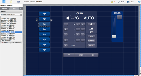
Besides the direct association of control buttons and data points, the DOMINO driver also automatically updates graphical objects that represent values or states of complex devices, like the DFCT temperature control unit. It will also automatically intercept buttons to manually set operation modes and temperature set-points.
DFDMX
You can define a standard HSYCO DMX server for each DFDMX module, then use the [[dmx]] and [[dmxrgb]] objects to control channels 1-64 of the DMX bus connected to the DFDMX module.
For example:
dmxServers = dmx
dmxServersId.dmx = domino.o8
Note that, instead of defining the dmxServersIP parameter, the dmxServersId is used to associate the DMX server with the id of the DFDMX module.
DFCC
Setting the powerdisplay option to true in Settings enables the automatic display in the GUI of the total real power measured by all DFCC modules connected to this DFCP.
Note that, if you have more than one DFCP gateway, you should enable this option for one gateway only.
UISET Actions
You can use any object that accepts a text attribute, usually [[text]] but also [[marquee]] and others, to automatically display the average real power measured by all DFCC modules connected to the DOMINO bus. These objects are updated even when the powerdisplay option is false.
| ID | Attribute | |
|---|---|---|
| energy.<n>.power | value | real power, followed by W. <n> is the sequential index (1 to 3) of the DFCC module. |
DFCT and DF8RIT
You can use the temp and tempmini objects to control DFCT or DF8RIT devices.
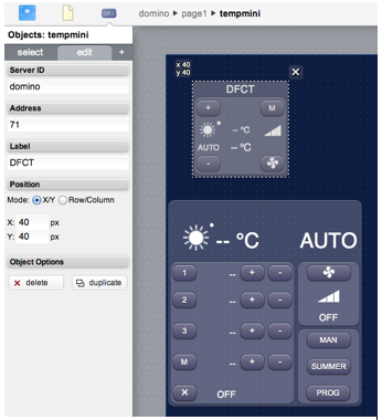
UISET Actions
You can use any object that accepts a text attribute, usually [[text]] but also [[marquee]] and others, like images, to automatically display the relevant information of all DFCT modules.
| ID | Attribute | Set to | Description |
|---|---|---|---|
| <address>.mode | value | SUMMER | summer mode (cooling) |
| WINTER | winter mode (heating) | ||
| <address>.mode.label.summer | visible | true | the DFCT is in summer mode |
| <address>.mode.label.winter | visible | true | the DFCT is in winter mode |
| <address>.status | value | OFF | zone off |
| ON | zone on | ||
| <address>.status.label.cooling | visible | true | if the zone is cooling |
| <address>.status.label.heating | visible | true | if the zone is heating |
| <address>.fan | value | OFF | fan off |
| MIN | minimum fan speed | ||
| MED | medium fan speed | ||
| MAX | maximum fan speed | ||
| <address>.fan.label.min | visible | true | the fan speed is min |
| <address>.fan.label.med | visible | true | the fan speed is med |
| <address>.fan.label.max | visible | true | the fan speed is max |
| <address>.fan.mode | value | MAN | manual fan mode |
| AUTO | auto fan mode | ||
| <address>.setpoint | value | 1,2,3 | active setpoint |
| MAN | manual setpoint | ||
| OFF | zone off | ||
| <address>.setpoint.label.1 | visible | true | setpoint 1 is active |
| <address>.setpoint.label.2 | visible | true | setpoint 2 is active |
| <address>.setpoint.label.3 | visible | true | setpoint 3 is active |
| <address>.setpoint.label.man | visible | true | manual setpoint is active |
| <address>.setpoint.label.off | visible | true | zone is off |
| <address>.setpoint.mode | value | MAN | manual setpoint mode |
| AUTO | auto setpoint mode | ||
| <address>.setpoint.temp | value | <value> | the active setpoint temperature, in Celsius degrees with one decimal digit, followed by " °C" |
| <address>.setpoint.temp.1 | value | <value> | the active setpoint 1 temperature, in Celsius degrees with one decimal digit, followed by " °C" |
| <address>.setpoint.temp.2 | value | <value> | the active setpoint 2 temperature, in Celsius degrees with one decimal digit, followed by " °C" |
| <address>.setpoint.temp.3 | value | <value> | the active setpoint 3 temperature, in Celsius degrees with one decimal digit, followed by " °C" |
| <address>.setpoint.temp.man | value | <value> | the manual setpoint temperature, in Celsius degrees with one decimal digit, followed by " °C" |
| <address>.temp | value | <temp> | the manual setpoint temperature, in Celsius degrees with one decimal digit, followed by " °C" |
| FAULT | fault/error condition |
USER Commands
There are several predefined buttons. Use any ordinary [[user]] object, setting the name and param fields based on this table.
| Name | Param | Action |
|---|---|---|
| <address> | mode | cycle through summer and winter mode |
| mode.summer | set summer mode (cooling) | |
| mode.winter | set winter mode (heating) | |
| fan | cycle through fan speeds and modes (auto, off, man/min, man/med, man/max, auto) | |
| <address>.setpoint | mode | cycle through the manual, automatic and off operation modes |
| mode.man | set manual operation mode | |
| mode.auto | set automatic operation mode | |
| mode.off | off mode | |
| temp.1.up | increase setpoint 1 temperature in 0.5C steps | |
| temp.1.down | decrease setpoint 1 temperature in 0.5C steps | |
| temp.1.<t> | setpoint 1 set to temperature t, in C/10 (0 <= t <= 355) | |
| temp.2.up | increase setpoint 2 temperature in 0.5C steps | |
| temp.2.down | decrease setpoint 2 temperature in 0.5C steps | |
| temp.2.<t> | setpoint 2 set to temperature t, in C/10 (0 <= t <= 355) | |
| temp.3.up | increase setpoint 3 temperature in 0.5C steps | |
| temp.3.down | decrease setpoint 3 temperature in 0.5C steps | |
| temp.3.<t> | setpoint 3 set to temperature t, in C/10 (0 <= t <= 355) | |
| temp.man.up | increase manual setpoint temperature in 0.5C steps | |
| temp.man.down | decrease manual setpoint temperature in 0.5C steps | |
| temp.man.<t> | manual setpoint set to temperature t, in C/10 (0 <= t <= 355) | |
| <address>.fan | mode | cycle through the manual and automatic fan speed modes |
| mode.man | set manual fan speed mode | |
| mode.auto | set automatic fan speed mode | |
| up | increase fan speed | |
| down | decrease fan speed | |
| min | set min fan speed | |
| med | set med fan speed | |
| max | set max fan speed | |
| off | fan off |
Using slider objects for DF8RIT shutter's position
When shutter control is enabled on the DF8RIT multifunction module, up to four addresses are used to read and set the shutters' position (goto function).
You can use the slider objects, slider|sliderv and slider|sliderh, to display and control the position. Remember that the shutters' position addresses are base_address + 1 to base_address + 4, where base_address is the address of the module. Set both the slider's ID and address to <server_name>.<base_address + N>, with N from 1 to 4.
For example, assuming that domino is the I/O Server ID, and the DF8RIT base address is 121, the slider's ID and address to control the first shutter (relays 1 and 2) should be domino.122.
Note that you can set the inverse attribute of the slider|sliderv object to true, in order to have the cursor at the top instead of bottom of the slider when the position is 0.
Using slider objects for DF4RI / DF4RIR shutter's position
When shutter control is enabled on the DF4RI multifunction module, up to two addresses are used to read and set the shutters' position (goto function).
You can use the slider objects, slider|sliderv and slider|sliderh, to display and control the position. Remember that the shutters' position addresses are base_address + 1 and base_address + 2, where base_address is the address of the module. Set both the slider's ID and address to <server_name>.<base_address + N>, with N from 1 to 2.
For example, assuming that domino is the I/O Server ID, and the DF8RIT base address is 100, the slider's ID and address to control the first shutter (relays 1 and 2) should be domino.101.
Note that you can set the inverse attribute of the [[slider|sliderv]] object to true, in order to have the cursor at the top instead of bottom of the slider when the position is 0.
DFTZ
You can use the tempmini object to control DFTZ devices.
You could also use the larger temp object, but some of its controls are not used with the DFTZ module.

UISET Actions
You can use any object that accepts a text attribute, usually text and others, like images, to automatically display the relevant information of all DFTZ modules.
| ID | Attribute | Set to | Description |
|---|---|---|---|
| <address>.mode | value | SUMMER | summer mode (cooling) |
| WINTER | winter mode (heating) | ||
| <address>.mode.label.summer | visible | true | the DFTZ is in summer mode |
| <address>.mode.label.winter | visible | true | the DFTZ is in winter mode |
| <address>.status | value | OFF | zone off |
| ON | zone on | ||
| <address>.status.label.off | visible | true | if the zone is not cooling or heating |
| <address>.status.label.cooling | visible | true | if the zone is cooling |
| <address>.status.label.heating | visible | true | if the zone is heating |
| <address>.setpoint | value | COM | comfort setpoint |
| MAN | manual setpoint | ||
| OFF | zone off | ||
| <address>.setpoint.label.1 | visible | true | comfort setpoint is active |
| <address>.setpoint.label.2 | visible | true | eco setpoint is active |
| <address>.setpoint.label.off | visible | true | zone is off |
| <address>.setpoint.temp | value | <temp> | the active setpoint temperature, in Celsius degrees with one decimal digit, followed by " °C" |
| <address>.setpoint.temp.1 | value | <temp> | the comfort setpoint temperature, in Celsius degrees with one decimal digit, followed by " °C" |
| <address>.setpoint.temp.2 | value | <temp> | the eco setpoint temperature, in Celsius degrees with one decimal digit, followed by " °C" |
| <address>.setpoint.temp.man | value | <temp> | the summer or winter setpoint temperature limit, in Celsius degrees with one decimal digit, followed by " °C" |
| <address>.temp | value | <temp> | the manual setpoint temperature, in Celsius degrees with one decimal digit, followed by " °C" |
| FAULT | fault/error condition |
USER Commands
There are several predefined buttons. Use any ordinary [[user]] object, setting the name and param fields based on this table.
| Name | Param | Action |
|---|---|---|
| <address> | mode | cycle through summer and winter mode |
| mode.summer | set summer mode (cooling) | |
| mode.winter | set winter mode (heating) | |
| <address>.setpoint | mode | cycle through the manual, automatic and off operation modes |
| mode.comfort | set comfort operation mode | |
| mode.eco | set eco operation mode | |
| mode.off | off mode | |
| temp.up | increase the active setpoint temperature in 0.5C steps | |
| temp.down | ddecrease the active setpoint temperature in 0.5C steps | |
| temp.<t> | active setpoint set to temperature t, in C/10 (0 <= t <= 355) | |
| temp.1.up | increase comfort setpoint temperature in 0.5C steps | |
| temp.1.down | decrease comfort setpoint temperature in 0.5C steps | |
| temp.1.<t> | comfort setpoint set to temperature t, in C/10 (0 <= t <= 355) | |
| temp.2.up | increase eco setpoint temperature in 0.5C steps | |
| temp.2.down | decrease eco setpoint temperature in 0.5C steps | |
| temp.2.<t> | eco setpoint set to temperature t, in C/10 (0 <= t<= 355) | |
| temp.man.up | increase setpoint temperature limit in 0.5C steps | |
| temp.man.down | decrease setpoint temperature limit in 0.5C steps | |
| temp.man.<t> | set-point temperature limit set to temperature t, in C/10 (0 <= t <= 355) |
DFTZ2
You can use the tempmini object to control DFTZ2 devices.
You could also use the larger temp object, but some of its controls are not used with the DFTZ2 module.
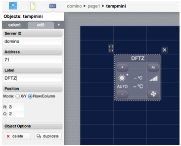
UISET Actions
You can use any object that accepts a text attribute, usually text but and others, like images, to automatically display the relevant information of all DFTZ2 modules.
| ID | Attribute | Set to | Description |
|---|---|---|---|
| <address>.mode | value | SUMMER | summer mode (cooling) |
| WINTER | winter mode (heating) | ||
| <address>.mode.label.summer | visible | true | the DFTZ2 is in summer mode |
| <address>.mode.label.winter | visible | true | the DFTZ2 is in winter mode |
| <address>.status | value | OFF | zone off |
| ON | zone on | ||
| <address>.status.label.off | visible | true | if the zone is not cooling or heating |
| <address>.status.label.cooling | visible | true | if the zone is cooling |
| <address>.status.label.heating | visible | true | if the zone is heating |
| <address>.setpoint.mode | value | COM | comfort setpoint |
| ECO | eco setpoint | ||
| OFF | zone off | ||
| <address>.setpoint.label.1 | visible | true | comfort setpoint is active |
| <address>.setpoint.label.2 | visible | true | eco setpoint is active |
| <address>.setpoint.label.off | visible | true | zone is off |
| <address>.setpoint.temp | value | <temp> | the active setpoint temperature, in Celsius degrees with one decimal digit, followed by " °C" |
| <address>.setpoint.temp | visible | true | if mode is not off |
| <address>.setpoint.temp.1 | value | <temp> | the comfort setpoint temperature, in Celsius degrees with one decimal digit, followed by " °C" |
| <address>.setpoint.temp.2 | value | <temp> | the eco setpoint temperature, in Celsius degrees with one decimal digit, followed by " °C" |
| <address>.setpoint.temp.man | value | <temp> | the summer or winter setpoint temperature limit, in Celsius degrees with one decimal digit, followed by " °C" |
| <address>.temp | value | <temp> | the current temperature, in Celsius degrees with one decimal digit, followed by " °C" |
| FAULT | fault/error condition | ||
| <address>.humidity | value | <temp> | the current relative humidity (%) |
| <address>.dewpoint | value | <temp> | the current dew point, in Celsius degrees with one decimal digit, followed by " °C" |
| <address>.limit.1 | value | <temp> | the dew point limit 1, in Celsius degrees with one decimal digit, followed by " °C" |
| <address>.limit.2 | value | <temp> | the dew point limit 2, in Celsius degrees with one decimal digit, followed by " °C" |
| <address>.fan | value | <temp> | the fan speed: OFF, MIN, MED, MAX |
| <address>.fan.mode | value | <temp> | the fan mode: AUTO, MAN |
| <address>.fan.label.min | visible | true | if fan speed is MIN |
| <address>.fan.label.med | visible | true | if fan speed is MED |
| <address>.fan.label.max | visible | true | if fan speed is MAX |
USER Commands
There are several predefined buttons. Use any ordinary button object, setting the name and param fields based on this table.
| Name | Param | Action |
|---|---|---|
| <address> | fan | cycle through fan speeds |
| mode | cycle through summer and winter mode | |
| mode.summer | set summer mode (cooling) | |
| mode.winter | set winter mode (heating) | |
| <address>.setpoint | mode | cycle through the manual, automatic and off operation modes |
| mode.comfort | set comfort operation mode | |
| mode.eco | set eco operation mode | |
| mode.off | off mode | |
| temp.up | increase the active setpoint temperature in 0.5C steps | |
| temp.down | ddecrease the active setpoint temperature in 0.5C steps | |
| temp.<t> | active setpoint set to temperature t, in C/10 (0 <= t <= 355) | |
| temp.1.up | increase comfort setpoint temperature in 0.5C steps | |
| temp.1.down | decrease comfort setpoint temperature in 0.5C steps | |
| temp.1.<t> | comfort setpoint set to temperature t, in C/10 (0 <= t <= 355) | |
| temp.2.up | increase eco setpoint temperature in 0.5C steps | |
| temp.2.down | decrease eco setpoint temperature in 0.5C steps | |
| temp.2.<t> | eco setpoint set to temperature t, in C/10 (0 <= t <= 355) | |
| temp.man.up | increase setpoint temperature limit in 0.5C steps | |
| temp.man.down | decrease setpoint temperature limit in 0.5C steps | |
| temp.man.<t> | set-point temperature limit set to temperature t, in C/10 (0 <= t <= 355) |
Release Notes
3.9.0
- support of AURORA
- new devicecommlog DFCP datapoint
- DFIGLASS i<address>.fault removed
- fixed a bug that, in some specific conditions, could interrupt input and output polling from DFDALI and DFDALI64; improved logging in verbose mode
3.8.0
- support of DFAM2
- support of DFANA-M/CC
- support of DFMB-C
- support of DFTZ2
- support for DTCT firmware versions >= 10.0 for daily programs read/write
- new "raw" datapoint allows to send a 2 byte raw command to the DFDALI64 module
- improved support for DFCP/DFH firmware upload
- fixed (temp) GUI object setpoint program
- workaround for DFH with fw < 4.0 that caused the clock=sync command to set an incorrect time on Sundays
3.7.0
- support of DFANA-M
- support of DFDALI64
- support of DFDIM
- support of DFLS smart mode
- support of DF4RI/DF4RIR virtual outputs
- support of DF8RIT configuration with temperature input address enabled and temperature control disabled
- support of position information and commands for DFTP, DFTP/I
- support of DFCP counters
- bus and modules fault detection
- high availability support for redundant DFH installations
- fixed "modulefault" data point of individual modules not working with DFH gateways
3.6.0
- added support for DFTA and DFTE
- DFIGLASS: added support for the optional temperature sensor, and other enhancements
- improved compatibility with DF4DV
- fixed a bug that could affect DF4RI/DF4RIR or DF8RIT modules with adjacent addresses and shutters defined
3.5.1
- added support for DF4DV
- added support for DF4RI / DF4RIR
- added support for DF8RIT
- added support for DFLS / DFLS-P
- fixed a bug that could cause erroneous readings of DFCC2 2'complement values
- DFANA updated to support negative active energy values (fw. 1.5 or later)
3.5.0
- added support for DFCP4
- fixed a bug that could cause erroneous readings of DFCC's 2'complements values
3.4.0
- improved communication error logging
- improved support of tools remote access
- events generated during startup if startupevents=true are now executed sequentially
- DFCC2 module support
- DFH module support
- fix: DFTZ user commands mode.comfort, mode.eco, mode.off not working
3.2.2
bug fixes:
- the toolspassword optional parameter was incorrectly converted to lower case
- fixed a bug that prevented reading the input pins of DF4RP/I and DF4RPR/I
3.2.1
- support for DFTZ
3.2.0
- support for DFIGLASS
- new "detectevents" option, generates forced events when a device is detected at start-up
- support for the toolspassword option, to allow DFCP-IDE and other tools secure remote access to the DFCP via HSYCO
- new clock datapoint to read the DFCP internal clock and set it to HSYCO's time
3.1.2
bug fixes:
- the (temp) object's DFCT configuration function was broken in HSYCO 3.1.0
- energy metering data point were not updated
3.1.1
- added support for DF4RP/I and DFDT
3.1.0
- added support for DFANA energy meter module
3.0.3
- optimized performance of DFCP’s registers status polling
3.0.1
- you can now limit the number of virtual points and registers read and written by HSYCO, and have access to all of the 1024 registers; defaults are unchanged
- added support for DF8IL, DFDI2B and DFRHT modules
3.0.0
- update DFDMX state at startup
- support for failover mode
1.2.0
- fixed bugs related to the DFDM and DFDI modules
- integration with the DMX server engine
- enhanced GUI support for DFCC and DFCT
1.1.0
- automatic generation of the device map in systemtopo.txt
- Web Editor support
- support for DFCP’s virtual data points and registers
- support for serial connection to the DFCP through the serial ports of HWg PortBox and ERxx network devices
1.0.0
- initial release
HSYCO and Home Systems Consulting are registered trademarks of Home Systems Consulting SpA. Java and JavaScript are registered trademarks of Oracle and/or its affiliates. DOMINO and DUEMMEGI are registered trademarks of DUEMMEGI SRL. Other products or company names can be trademarks or registered trademarks of other companies and are used for demonstrative purposes only, with no violation intent.