Chapter 14: The Wiring Editor
The Wiring Editor is HSYCO's no-code automation tool. Where EVENTS (Chapter 6) asks you to write rules as text, the Wiring Editor lets you connect an input to an output visually, with no code at all. It covers the automations that come up most often in a home or small building: make a button toggle a light, dim a lamp from one button, drive a blind from a pair of buttons, or run a scenario on a schedule.
Open it from the Manager, or by browsing directly to the project page named wiring.
14.1 Inputs, Outputs, and Wirings
The editor works with three lists.
Inputs are things that trigger something: a readable I/O Server datapoint, a USER event from a button, or a scheduler event. Each input is either Binary 0/1 (a button, a contact) or Level (a sensor value). Several inputs can be combined into an inputs group, which behaves as their logical OR, useful for controlling one light from two switches.
Outputs are things you can act on: a writable datapoint, a USER event, or an outputs group that writes the same value to all its members. Each output has a type, On/Off, Dimmer, or Blind, and the type decides which functions are available.
Wirings are the connections. A wiring links one or more inputs to one output and applies a function. On/Off wirings offer Toggle, 2-Ways (separate on and off inputs), Push-button (output active only while the input is held, with optional Delay and Hold), and Direct (output follows the input). Dimmer wirings add Cycle, 2-Ways, 3-Ways, and Level functions that treat a short press differently from a held button; Blind wirings offer the same Cycle, 2-Ways, and 3-Ways functions, but not Level.
A fourth wiring type, Scenario, works differently: instead of an input driving an output continuously, it plays back a pre-recorded state. Set your output, most often an output group mixing lights, dimmers, and blinds, to the state you want (everything off and the blinds closed, for an "exit" scenario), then create a Scenario wiring choosing the activating input and that output; HSYCO records the current state of the output(s) at that moment. If the input is a scheduler, you can choose whether the scenario plays back when the scheduler activates or deactivates, useful for pairing two scenarios, one per transition, to the same schedule. To update a recorded scenario later, set the output(s) to the new desired state, then long-press the wiring to open its edit panel and click Record.
You build the interface with the buttons on each column: + at the top of the Inputs or Outputs list adds an entry (an I/O datapoint, a USER button, a scheduler, or a group), and the I ↔ O button above the Wirings list creates a wiring from the inputs and output you select.
14.2 First-Run Behaviour and Locking
The first time you open the Wiring Editor it pre-populates the input and output lists from your configured I/O Servers, KNX and DUMMY datapoints and so on. After you add or remove anything it stops auto-updating, so you tidy the lists once and then maintain them by hand. You can also filter which datapoints appear using text files placed in a wiring folder in HSYCO's root directory: whitelist.in.txt and whitelist.out.txt list the input and output IDs to include, while blacklist.in.txt and blacklist.out.txt list IDs to exclude from the automatically detected set. An empty whitelist file gets filled in automatically with every auto-detected ID. Changes to these files take effect only after a restart. The icon in the bottom-left corner takes a named backup of the whole wiring configuration.
By default the editor runs in expert mode, with every function available. You can lock it down so that an end user can create and change wirings but cannot add, edit, or delete the underlying input and output datapoints, keeping them away from sensitive addresses.
14.3 Working Alongside EVENTS
The two tools are not exclusive. A wiring can target a USER event as its output, so a visually built connection can hand off to an EVENTS rule for anything the Wiring Editor cannot express. A scheduler created for a wiring is the same scheduler object covered in Chapter 9. Use the Wiring Editor for simple, repetitive connections; drop into EVENTS when the logic needs conditions, timers, or calculations.
14.4 Recipe: Linking Three Lights Together
This recipe wires one light so that switching it on or off also switches two other lights, using the DUMMY I/O Server already configured in Chapter 4 (lights = 5).
Step 1: Add three lights in the Project Editor
On a project page, add three objects bound to dummy.light.1, dummy.light.2, and dummy.light.3 (a Button with Action set to datapoint works well) so you can watch all three react.
Step 2: Add the input
Open the Wiring Editor. Click + above the Inputs column, choose IO Server datapoint, and add dummy.light.1. Name it light 1 and set its type to Binary 0/1.
Step 3: Group the other two lights as one output
Click + above the Outputs column and choose Outputs group. Name it light group and add dummy.light.2 and dummy.light.3 as members (Figure 51).
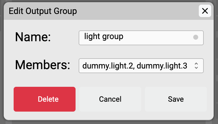
Edit Output Group: light group with dummy.light.2 and dummy.light.3 as members
Step 4: Create the wiring
Click the I ↔ O button above the Wirings column and set (Figure 52):
- Name:
lights - Output type:
On/Off - Function:
Direct - Input:
light 1 - Output:
light group
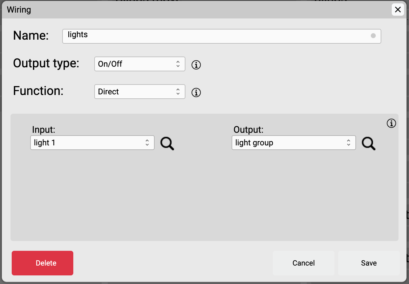
The Wiring dialog: Direct function from light 1 to light group
Save (Figure 53).
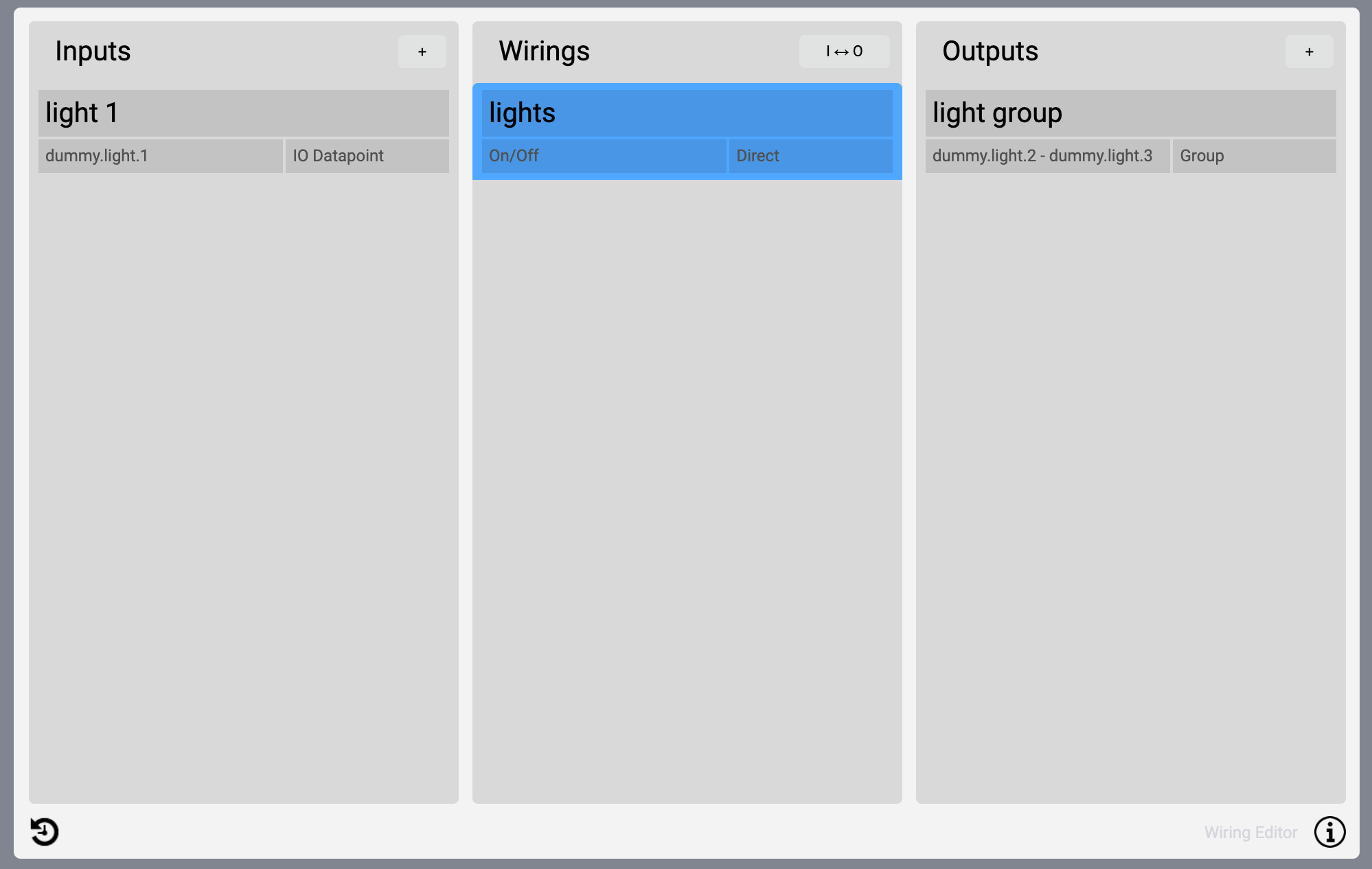
The finished wiring, with one input and one grouped output
Step 5: Test
Open Status Browser (or run the project) and set dummy.light.1 to 1. Both dummy.light.2 and dummy.light.3 turn on with it. Set dummy.light.1 back to 0 and both follow it off.
Why Direct
The Direct function makes the output copy whatever state the input is in, rather than toggling or requiring a held press. Because the wiring only reads from light 1, the effect is one-way: light 1 drives the group, but changing dummy.light.2 or dummy.light.3 directly, from Status Browser or their own buttons, does not feed back into light 1.
14.5 Recipe: Two-Button Blind Control
This recipe drives a pair of blinds with two real buttons, one for up and one for down, using the DUMMY automations already configured in Chapter 4 (automations = 2, giving you dummy.autom.1 and dummy.autom.2).
Step 1: Add the buttons in the Project Editor
Add two Button objects and set Action to command on both, the same USER-event mechanism covered in Chapter 7. Give the first button ID and Name blind.up and Parameter up; give the second ID and Name blind.down and Parameter down. If you want holding a button down to keep the blind moving, also set Repeat to enabled on both, the Wiring Editor needs the button to keep firing while it's held.
Step 2: Add the two inputs
In the Wiring Editor, click + above Inputs twice. Choose User button as the type both times: enter blind.up as the ID and name it blind up, then enter blind.down as the ID and name it blind down.
Step 3: Group the blinds as one output
Click + above Outputs and choose Outputs group. Name it blinds and add dummy.autom.1 and dummy.autom.2 as members, so both move together.
Step 4: Create the wiring
Click I ↔ O and set (Figure 54):
- Name:
Blinds move - Output type:
Blind - Function:
2-Ways - Input - up/stop:
blind up - Input - down/stop:
blind down - Output:
blinds
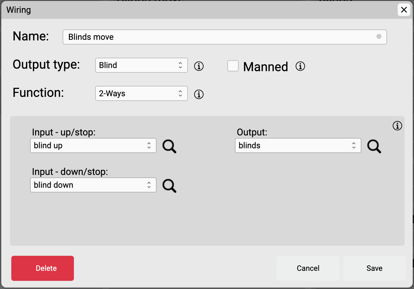
The Wiring dialog: 2-Ways function with separate up and down inputs
Save (Figure 55).
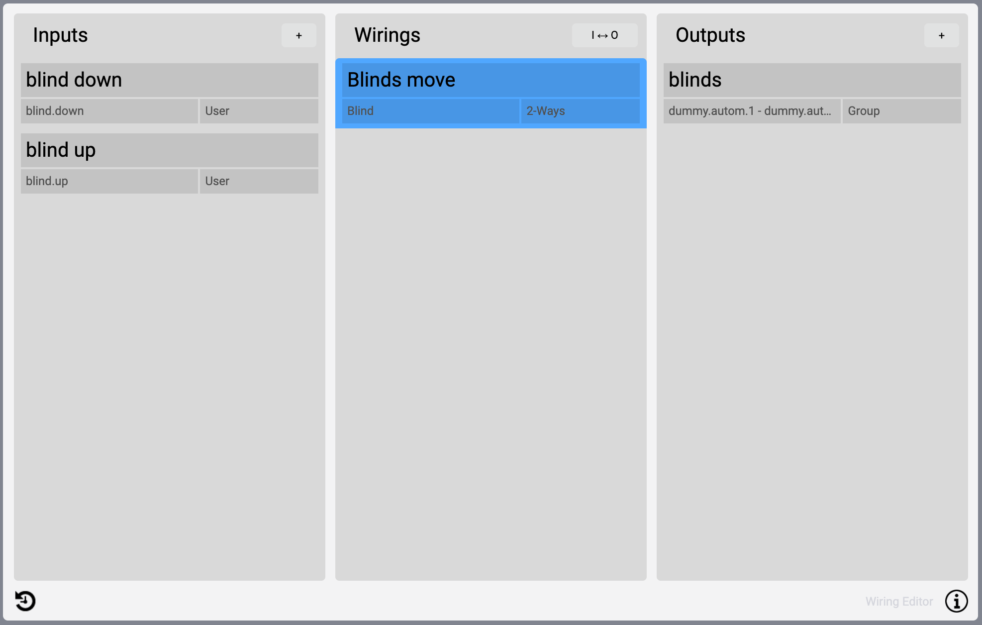
The finished blind wiring: two User button inputs into one grouped Blind output
Step 5: Test
Press the blind.up button: both blinds start rolling up and keep going until they reach the end, or until you press blind.up again, which stops them, that's the "/stop" half of the up input. Hold the button down instead, with Repeat enabled, and the blinds move only while it's held, stopping the instant you release it. blind.down works the same way for the down direction.
Manned mode
If you'd rather the blinds move only while a button is actually held, like a dead-man's switch, check Manned on the wiring. This turns off the short-press "roll to the end, press again to stop" behavior entirely.