Chapter 10: Protocols Integration
10.1 KNX Integration
KNX is one of the most widely used building automation standards in the world. This section explains how to connect HSYCO to a KNX installation, configure datapoints, and create working automation with KNX devices.
10.1.1 KNX Protocol Overview
KNX is a standardized protocol for building automation and control. It uses a decentralized architecture. Instead of a central controller telling devices what to do, KNX devices communicate directly with each other using group addresses. Think of group addresses as channels that multiple devices can listen to and broadcast on.
For example, when you press a KNX switch, it sends a message to a group address like 0/1/5. Any device configured to listen to that address receives the message and acts on it. A light actuator listening to 0/1/5 turns on the light. A scene controller listening to the same address might activate a lighting scene.
Group Addresses
Group addresses are the foundation of KNX communication. Every function in a KNX installation has a group address.
Group addresses use a three-level format: main group / middle group / sub group. For example:
-
0/0/1 - Kitchen ceiling light
-
0/0/2 - Kitchen dimmer
-
0/1/1 - Living room blind
The numbers themselves don't have meaning, they’re simply identifiers you assign during programming. The KNX standard supports addresses from 0/0/1 to 31/7/255.
Datapoint Types (DPT)
Every group address has a datapoint type that defines how data is formatted. Common DPT types include:
-
DPT 1: 1-bit boolean (on/off, true/false), used for switches, binary sensors
-
DPT 5: 8-bit unsigned value (0-255), used for dimmer levels, blind positions
-
DPT 9: 2-byte floating point, used for temperature values, humidity
-
DPT 7: 2-byte unsigned value, used for counters
The DPT tells HSYCO how to interpret the data. A value of 255 in a DPT 5 datapoint might mean 100% brightness for a dimmer, or fully closed for a blind, depending on the configuration.
Programming Requirement
The KNX installation must be programmed using ETS (Engineering Tool Software), the official KNX programming tool. ETS defines which devices exist, what group addresses they use, and how they communicate. HSYCO does not replace ETS. You use ETS to program the KNX installation, then configure HSYCO to interact with the programmed group addresses.
10.1.2 Configuring the KNX I/O Server
To connect HSYCO to KNX:
-
Open the Manager and go to Settings.
-
Select I/O Servers from the left sidebar.
-
Click the + icon to add a new I/O Server.
-
Select KNX as the type.
-
Enter a Name (for example, knx).
-
Click OK.
The KNX I/O Server appears in the list (Figure 38).
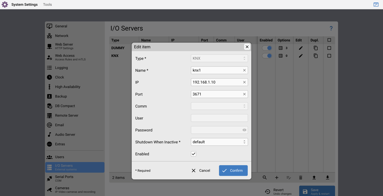
The KNX I/O Server's Settings page
Communication Parameters
Configure the connection to your KNX/IP gateway:
-
IP Address: Enter the IP address of your KNX/IP gateway (for example, 192.168.1.51)
-
IP Port: Leave blank to use the default port 3671, or enter a custom port if your gateway uses a different port
-
Shutdown when inactive: Leave at the default value (false) for most installations
Options
The KNX I/O Server has several options that control its behavior:
startupevents
-
true: Generate IO events during the startup phase, while HSYCO is still reading initial values from KNX devices
-
false (default): Only generate events after HSYCO is fully synchronized with the KNX system
Use false for most installations to avoid triggering unwanted automation during startup.
discovery
-
true (default): Automatically add detected DPT 1 datapoints and virtual datapoints to catalog.json (see Chapter 12)
-
false: Manual management of catalog.json
Use true to automatically populate the device list for the user interface.
localport
-
blank (default): HSYCO uses its standard local port to reach the gateway
-
<port number>: Fix the local port HSYCO uses to communicate with the KNXnet/IP gateway. Setting it may be necessary when the gateway is reached through network address translation (NAT).
fromevents
-
true: Generate events reporting commands sent on the KNX bus, including the source address
-
false (default): Only generate events for datapoint value changes
Enable this when you need to know which physical KNX device sent a command.
readaftercommand
-
true: Force a read of the datapoint value after sending a command to it
-
false (default): Assume commands are successful without reading back
Enable this if you need immediate confirmation that a command was executed.
initreadinterval
-
0 (default): No delay between read requests during initialization
-
milliseconds: Time interval between datapoint value read requests during startup
Use a small value (like 50-100ms) if your KNX/IP gateway has trouble handling many rapid read requests, especially during the driver startup phase.
decimals
-
1 (default): Show one decimal digit for floating point values
-
0-9: Number of decimal digits to display
Adjust this for temperature sensors or other analog values.
Saving the Configuration
After configuring all parameters:
-
Click Save at the bottom of the Settings page.
-
Click Restart to restart HSYCO.
HSYCO will start the KNX I/O Server and attempt to connect to the gateway.
The knxtopo.txt File
The knxtopo.txt file contains the configuration of all KNX datapoints. There are two ways to populate this file:
-
Import an ETS project using the KNX Utility (recommended).
-
Manually edit knxtopo.txt.
The file structure is straightforward. Each line defines one datapoint:
<io_server_id>.<group_address> : dpt = {1 ... 18}; id = <id>; [priority = {low|normal|urgent};] [read={true|false};] [description = <description_text>]
For example:
knx.0/0/1 : dpt = 1; id = dpt1; priority = low; read=true; description = Kitchen light
This defines:
-
Group address 0/0/1
-
DPT type 1 (boolean)
-
ID dpt1 (the datapoint will be knx.dpt1)
-
Priority low
-
Read at startup (read=true)
-
Description "Kitchen light"
Raw Group Addresses
You don't have to declare a group address in knxtopo.txt before using it. With discovery enabled (the default), HSYCO automatically picks up any DPT 1 group address it sees on the bus and exposes it directly as a datapoint named after its raw address, no id required:
IO knx.1/2/3 = 1 : LOG = "group 1/2/3 turned on"
This is handy for a quick test or a one-off reference to an address you haven't bothered to name yet. You'll see this raw-address style used later in this chapter (Section 10.4.3) when bridging KNX to other protocols. For anything you'll reuse or want a reader-friendly name for, declare an id as shown above instead.
Virtual Datapoints
Virtual datapoints combine multiple group addresses into a single logical device. For example, a KNX dimmer typically uses multiple group addresses:
-
One for on/off feedback
-
One for on/off commands
-
One for brightness level feedback
-
One for brightness level commands
Instead of managing four separate datapoints, you create a virtual dimmer datapoint that references all four addresses.
Virtual datapoints are defined with different syntax:
Light virtual datapoint:
<io_server_id>.light.<id> : fb = <feedback_address>; cmd = <command_address>; on = {1|0}; description = <text>
Example:
knx.light.1 : fb = 0/1/1; cmd = 0/1/2; on = 1; description = Kitchen ceiling light
Dimmer virtual datapoint:
<io_server_id>.dimmer.<id> : fb.level = <level_fb>; fb.onoff = <onoff_fb>; cmd.level = <level_cmd>; cmd.onoff = <onoff_cmd>; cmd.step = <step_cmd>; on = {1|0}; stepval = {1|2|3|4|5|6|7}; description = <text>
Example:
knx.dimmer.1 : fb.level = 0/1/3; fb.onoff = 0/1/4; cmd.level = 0/1/5; cmd.onoff = 0/1/6; cmd.step = 1/0/2; on = 1; stepval = 3; description = Living room dimmer
Automation (blinds) virtual datapoint:
<io_server_id>.autom.<id> : fb.position = <pos_fb>; fb.updown = <updown_fb>; cmd.updown = <updown_cmd>; cmd.position = <pos_cmd>; cmd.stop = <stop_cmd>; up = {0|1}; closed = {255|0}; position = {true|false}; trip = <seconds>; description = <text>
Example:
knx.autom.1 : fb.position = 0/1/17; fb.updown = 0/1/13; cmd.updown = 0/1/20; cmd.position = 0/1/21; cmd.stop = 0/1/19; up = 0; closed = 255; position = false; trip = 60; description = Bedroom blinds
The parameters control how the automation behaves:
-
up: Which value (0 or 1) represents upward movement
-
closed: Which value (0 or 255) represents fully closed position
-
position: Whether position feedback is enabled
-
trip: Travel time in seconds from fully open to fully closed
You can manually edit knxtopo.txt using the File Manager, but the easier approach is to import from ETS.
10.1.3 Importing ETS Projects
The KNX Utility provides a graphical interface to import ETS project files and automatically populate knxtopo.txt. Whenever a KNX I/O server is defined in HSYCO, the KNX Utility will appear among the applications of the manager.
Open the application and select the KNX I/O Server to be configured in the select field in the top-right corner. If only one KNX I/O Server is defined it will be automatically selected.
Configuring Import Options
The Import dialog opens with several options (Figure 39):
-
Update Matching Datapoints: Compares the existing and imported KNX Datapoints to look for address or description matches. If found, related Datapoints will be updated, non-matching imported.
-
Delete Non-Matching Datapoints: Deletes any existing Datapoints that do not match any of the imported ones.
-
Description Keywords: Words that are looked for in the Datapoint description. If found, the related 'Read' attribute will automatically be set to 'True', otherwise to 'False'.
-
Delete Virtual Datapoints: If set, all defined Virtual Datapoints will be deleted before importing.
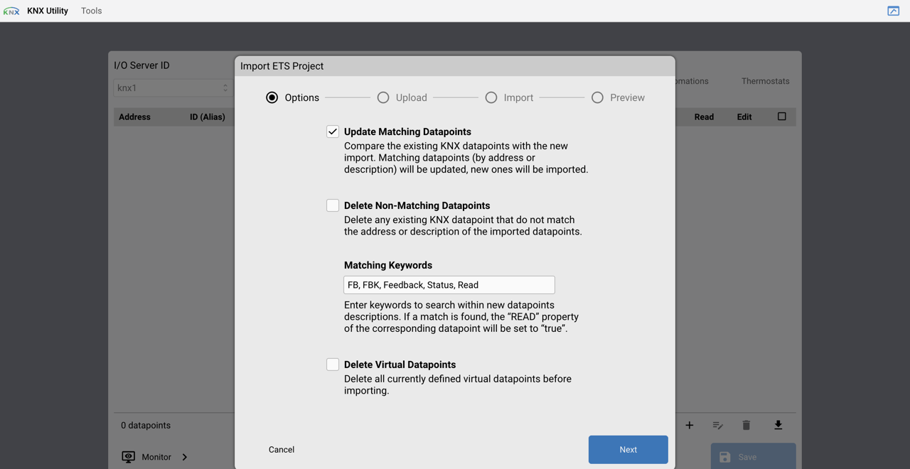
The KNX Utility's Import ETS Project dialog
Reviewing and Confirming the Import
Click Next to see the import preview. If Update Matching Datapoints or Delete Non-Matching Datapoints were selected, a preview of the Datapoints that will be imported is shown. It shows new, deleted, updated, missing and skipped Datapoints.
From the New table, you can deselect Datapoints to exclude them from the import. The No DPT table stores all Datapoint whose DPT is missing. By clicking the DPT cell, it is possible to in-line edit the DPT type directly before import.
When done, press Confirm to import all selected Datapoints. This procedure will create a datapoint for each imported one, with the corresponding DPT Type and attributes.
10.1.4 Recipe: Controlling KNX Lights
This recipe shows how to control a KNX light using HSYCO EVENTS programming.
What You Need
-
A KNX I/O Server configured and connected (connection = online in Status Browser)
-
A KNX group address configured in ETS (for example, 0/0/1)
-
The group address must be DPT 1 (boolean)
Step 1: Define the Datapoint in knxtopo.txt
Open File Manager, navigate to knxtopo.txt, and add:
knx.light.1 : fb = 0/0/2; cmd = 0/0/1; on = 1; description = Light 1
This creates datapoint knx.light.1 mapped to group address 0/0/1.
Save the file and restart HSYCO.
Step 2: Control the Light with EVENTS
Open the Code Editor and add EVENTS code.
Turn on the light at 7:00 AM:
TIME = 0700 : IO knx.light.1 = 1
Turn off the light at 11:00 PM:
TIME = 2300 : IO knx.light.1 = 0
Toggle the light when a USER button is pressed:
USER mybutton : IO knx.light.1 = flip
The flip value inverts the current state of the datapoint.
React when the light state changes
IO knx.light.1 = 1 : LOG = Light turned on
IO knx.light.1 = 0 : LOG = Light turned off
This logs a message whenever the light state changes, whether the command came from HSYCO or from a physical KNX switch.
Step 3: Verify in Status Browser
Open Status Browser and search for knx.light.1. You should see the datapoint with its current value and timestamp.
10.1.5 Recipe: KNX Blinds with Position Feedback
This recipe shows how to control KNX blinds with position feedback using a virtual automation datapoint.
What You Need
-
A KNX I/O Server configured and connected
-
KNX blinds with multiple group addresses for control and feedback
-
Group addresses configured in ETS
Step 1: Create the Virtual Automation Datapoint
The virtual automation datapoint links multiple group addresses into a single logical device. Open File Manager, navigate to knxtopo.txt, and add:
knx.autom.1 : fb.position = 0/1/17; fb.updown = 0/1/13; cmd.updown = 0/1/20; cmd.position = 0/1/21; cmd.stop = 0/1/19; up = 0; closed = 255; position = true; trip = 60; description = Autom 1
Parameters:
-
fb.position: Position feedback datapoint address (must be DPT 5)
-
fb.updown: Up/down direction feedback address (must be DPT 1)
-
cmd.updown: Up/down command address (must be DPT 1)
-
cmd.position: Position command address (must be DPT 5)
-
cmd.stop: Stop command address (must be DPT 1)
-
up: Which value (0 or 1) represents upward movement
-
closed: Which value (0 or 255) represents fully closed position
-
position: Whether position feedback is enabled (true or false)
-
trip: Travel time in seconds from fully open to fully closed
Save knxtopo.txt and restart HSYCO.
Step 2: Control the Blinds with EVENTS
Open the Code Editor and add EVENTS code.
Move to a specific position (0% to 100%):
TIME = 0700 : IO knx.autom.1 = 0%
TIME = 2200 : IO knx.autom.1 = 100%
USER halfbutton : IO knx.autom.1 = 50%
Direction commands:
USER openbutton : IO knx.autom.1 = up
USER closebutton : IO knx.autom.1 = down
Stop the automation:
USER stopbutton : IO knx.autom.1 = stop
Step 3: Understanding Position Feedback
When position feedback is enabled (position = true), the datapoint value includes movement indicators:
-
0% ... 100%: The automation is stopped at the reported position
-
0%+ ... 100%+: The automation is at the reported position and is closing
-
0%- ... 100%-: The automation is at the reported position and is opening
React to position changes:
IO knx.autom.1 = 100% : LOG = Blinds fully closed
IO knx.autom.1 = 0% : LOG = Blinds fully open
Step 4: Verify in Status Browser
Open Status Browser and search for knx.autom.1. You should see the datapoint with its current position value (for example, 50%, 50%+, or 50%-).
10.1.6 Recipe: Reading KNX Temperature Sensors
This recipe shows how to read temperature values from KNX sensors using HSYCO.
What You Need
-
A KNX I/O Server configured and connected
-
KNX temperature sensors with group addresses configured in ETS
-
Temperature sensors must use DPT 9 (2-byte floating point)
Step 1: Define the Datapoints in knxtopo.txt
Open File Manager, navigate to knxtopo.txt, and add:
knx.0/2/1 : dpt = 9; id = dpt2; read=true; description = Datapoint X
knx.0/2/2 : dpt = 9; id = dpt3; read=true; description = Datapoint X
This creates datapoints knx.dpt2 and knx.dpt3 for the two temperature sensors. The read=true parameter means HSYCO reads the value at startup.
Step 2: Adjust Decimal Precision (Optional)
To control how many decimal digits are displayed for floating point values, set the decimals option in the KNX I/O Server settings. The default is 1 decimal digit. Floating point numbers are rounded.
Step 3: Save and Restart
Save knxtopo.txt and restart HSYCO to load the new datapoints.
Step 4: Force Reading Values
To force HSYCO to read the current value from the KNX bus:
IO knx.dpt2 = read
You can read multiple datapoints with a single command:
IO knx.dpt2 knx.dpt3 = read
Step 5: React to Temperature Changes
Use stable events (comparison operators) to trigger actions based on temperature values:
IO knx.dpt2 < 20 : LOG = Temperature below 20
IO knx.dpt2 >= 22 : LOG = Temperature at or above 22
Step 6: Update UI Elements
Update a UI text object when temperature changes:
IO knx.dpt2 : UISET temp.text = IO knx.dpt2
Step 7: Log Temperature Data
Record temperature values to data loggers:
IO knx.dpt2 : DATALOGGER temps = IO knx.dpt2
Verify in Status Browser
Open Status Browser and search for knx.dpt2 and knx.dpt3. You should see the datapoints with their current temperature values and timestamps.
10.2 Modbus Integration
10.2.1 Protocol Overview
Modbus is a messaging structure used to establish master-slave/client-server communication between intelligent devices. It is a de facto standard in industrial and building automation. The protocol defines how devices exchange data: one device acts as the master (or client), which sends requests, and one or more devices act as slaves (or servers), which respond. HSYCO supports two Modbus roles: As a Modbus Client, HSYCO acts as the master, asking Modbus devices (slaves) for data, or as a Modbus Server, HSYCO holds the Modbus table itself, allowing external Modbus clients to read data from HSYCO as if it were a Modbus device.
Modbus TCP vs Modbus RTU
Modbus comes in two main variants. Modbus RTU is the original serial version, designed to run over RS-485 cables, the kind of wiring you might find connecting meters and controllers in older installations or on an industrial floor. Modbus TCP/IP takes the same Modbus instruction set and wraps it in standard TCP/IP, so devices can communicate over a regular network. HSYCO supports both variants. This chapter focuses on Modbus TCP, which is the most common choice for new installations and for devices that connect through a network gateway. Modbus RTU is also supported for direct serial connections, and the concepts in this chapter apply to both, the main difference is how you configure the communication parameters in Settings.
Note: Unlike KNX, which pushes updates automatically when a device changes state, Modbus is not asynchronous. Because the Modbus protocol is based on polling, you always have to request a read to tell the driver to actually read the data and eventually generate an event on the associated datapoint if the data has changed. This means you will always need to configure a polling mechanism, either using the Modbus Utility or EVENTS, to get fresh data from your devices.
HSYCO supports both Modbus TCP and Modbus RTU, acting as a Modbus master in both cases. When you configure a MODBUSTCP I/O Server, HSYCO connects to your device or gateway as a client and polls it for data (Figure 40).
There is also something worth knowing if you are integrating with other systems: HSYCO can act as both a Modbus client and a Modbus server at the same time. Using a separate MODBUSTCPSERVER I/O Server, HSYCO can expose its own internal data tables to external Modbus clients, for example, a third-party building management system that wants to read HSYCO datapoints via Modbus. This chapter concentrates on the client side (reading and controlling external devices), which is the most common use case for home and building automation.
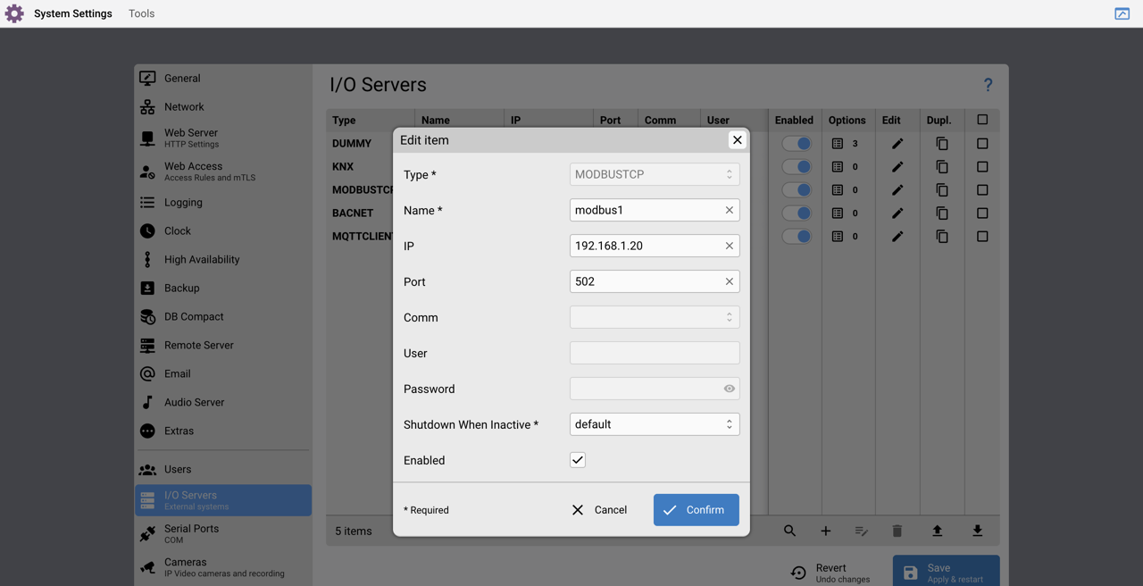
A Modbus I/O Server's Settings page
10.2.2 Understanding Modbus Basics
Before you start connecting devices, it helps to understand a few fundamental concepts about how Modbus organises data. You do not need to be a protocol expert, but knowing the difference between a coil and a holding register will save you time when you look up your device's documentation.
Register Types
Modbus devices organise their data into four types of storage, each with a different purpose and access mode. When you look up your device's documentation or register map, every register will belong to one of these four types:
Coils are single-bit values you can both read and write, on or off. They are used for outputs and controls.
Discrete Inputs are also single-bit, but read-only. They report the state of inputs coming into the device.
Input Registers are 16-bit values that are read-only. They carry measurements and data produced by the device.
Holding Registers are 16-bit values you can both read and write. They are used for setpoints, configuration values, and anything you need to both read back and change.
Data Types
A register on its own is just 16 bits of storage. What those bits mean depends on the data type you specify when reading. Some values fit in a single register, others span two or four consecutive registers.
The x variants exist because some devices send multi-register values with the least significant word first rather than the most significant. If a standard read gives you a nonsensical number, switching to the x variant of the same type is the first thing to try.
| Type Code | Description | Range | Registers |
|---|---|---|---|
ushort | Unsigned short integer | 0 … 65535 | 1 |
short | Signed short integer | −32768 … +32767 | 1 |
uint | Unsigned integer | 0 … 2³²−1 | 2 |
uintx | Unsigned integer, low word first | 0 … 2³²−1 | 2 |
ulong | Unsigned long integer | 0 … 2⁶⁴−1 | 4 |
ulongx | Unsigned long integer, low word first | 0 … 2⁶⁴−1 | 4 |
int | Signed integer | −2³¹ … 2³¹−1 | 2 |
intx | Signed integer, low word first | −2³¹ … 2³¹−1 | 2 |
long | Signed long integer | −2⁶³ … 2⁶³−1 | 4 |
longx | Signed long integer, low word first | −2⁶³ … 2⁶³−1 | 4 |
float | IEEE 754 floating point | signed decimal | 2 |
floatx | IEEE 754 floating point, low word first | signed decimal | 2 |
Datapoint Naming
All HSYCO Modbus client datapoints follow the same pattern:
<io_server_id>.<unitid>.<address>
The unitid is the Modbus slave address of the device, a number from 1 to 247. The address is the register address you are reading. So if your I/O Server is named modbus, your device has Unit ID 1, and you are reading register address 100, the datapoint is modbus.1.100.
Note: By default, when HSYCO reads a register and stores the result, the response datapoint name is just <io_server_id>.<unitid>.<address>. When extendednames is set to true, the response datapoint gets an additional postfix with the two-digit function code, for example modbus.1.100.03 for a holding register read. This is useful when you need to distinguish reads done with different function codes on the same address. For most installations you will not need it.
Reading Individual Bits: The bitshort Convention
Sometimes a single register encodes multiple pieces of information packed as individual bits, a status register where each bit means something different. HSYCO handles this with the bitshort, bitint, and bitlong format options, which read 1, 2, or 4 registers respectively and expose each bit as a separate sub-datapoint.
The sub-datapoints are named by appending a dot and a number to the base datapoint. The numbering follows this exact mapping:
| Register bit | 15 | 14 | 13 | 12 | 11 | 10 | 9 | 8 |
|---|---|---|---|---|---|---|---|---|
| Sub-datapoint | .8 | .7 | .6 | .5 | .4 | .3 | .2 | .1 |
| Register bit | 7 | 6 | 5 | 4 | 3 | 2 | 1 | 0 |
|---|---|---|---|---|---|---|---|---|
| Sub-datapoint | .16 | .15 | .14 | .13 | .12 | .11 | .10 | .9 |
10.2.3 HSYCO as a Modbus Server
So far this chapter has covered HSYCO as a Modbus client; connecting to external devices and reading or writing their registers. But HSYCO can also go the other direction. With the MODBUSTCPSERVER I/O Server, HSYCO implements a Modbus TCP/IP server, allowing external Modbus clients to connect to HSYCO and perform any standard Modbus function.
The Internal Data Tables
When HSYCO acts as a Modbus server it maintains four internal data tables, the same four types that exist on any Modbus device. Each table has its own suffix in the datapoint name:
The mode describes what external Modbus clients can do. The discrete inputs and input registers tables can be read by a Modbus client, and written locally from EVENTS to set their values. The coils and holding registers tables can be read or written by a Modbus client, and also written locally from EVENTS.
| Table | Suffix | Object Type | Mode (for external clients) |
|---|---|---|---|
| Discrete Inputs | .di | Single bit | Read only |
| Coils | .co | Single bit | Read / Write |
| Input Registers | .ir | 16-bit word | Read only |
| Holding Registers | .hr | 16-bit word | Read / Write |
The datapoint naming follows the same base pattern as everywhere else in HSYCO, with the table suffix appended to the address:
<io_server_id>.<unitid>.<address>.<table_suffix>
For example, if your server I/O Server is named mserver, Unit ID 1, holding register at address 1:
mserver.1.1.hr
Writing Values into the Tables
From EVENTS, you write values into HSYCO's internal tables the same way you would write to any datapoint. You specify the data type as part of the value:
# Write value 1 as an unsigned short into holding register 1
INIT : IO mserver.1.1.hr = "ushort:1"
# Write bit value 1 into discrete input register 1000
INIT : IO mserver.1.1000.di = "bit:1"
External Modbus clients connected to HSYCO can then read those values from the corresponding registers.
Subscribing for Events
When an external client writes to one of HSYCO's internal tables, HSYCO will only generate an IO event for that register if you have subscribed to it first. Without a subscription, the value is updated in the table but no event fires and your EVENTS rules cannot react to it.
Subscribing is done with a write to the register's datapoint using subscribe:<datatype>. The standard pattern is to set up subscriptions when the server connection comes online:
IO mserver.connection = online OR INIT : IO mserver.1.2.hr = subscribe:ushort
After this, every time an external client writes to holding register 2 on Unit ID 1, HSYCO generates an IO event on mserver.1.2.hr and your EVENTS rules can react to it.
Holding registers support subscriptions for all the standard data types: subscribe:ushort, subscribe:uint, subscribe:ulong, subscribe:short, subscribe:int, subscribe:long, subscribe:float, subscribe:hex, and subscribe:bits.
Client and Server at the Same Time
You can run both a MODBUSTCP client and a MODBUSTCPSERVER in the same HSYCO installation. For example, a client reading a value from an external device while the server exposes registers that another system can write to
# Client reads a value from an external device
INIT : IO mclient.1.2 = ushort:2044
# Subscribe to react when an external client writes to the server table
IO mserver.connection = online OR INIT : IO mserver.1.2.hr = subscribe:ushort
10.2.4 Recipe: Reading an Energy Meter via Modbus RTU
This recipe walks through connecting HSYCO to a Modbus RTU energy meter over a local RS-485 serial port, polling a register, and applying a transformation to the value in EVENTS. The example uses an HSYCO Strato Pi Max server with an RS-485 port.
Step 1: Declare the Serial Port
Before you can use Modbus RTU, HSYCO needs to know about the serial port the RS-485 line is connected to. Serial ports are configured in the Settings application under Serial Ports, and stored in hsyco.ini.
For a Strato Pi Max with an RS-485 port, the configuration looks like this:
CommPorts = rs485
CommPort.rs485.Type = serial
CommPort.rs485.Id = x2-rs485-1-1.5.1:1.0
CommPort.rs485.Params = 38400,8,2,0,0
The CommPort.rs485.Params value sets the serial communication parameters in the order: baud rate, data bits, stop bits, parity, flow control. In this case: 38400 baud, 8 data bits, 2 stop bits, no parity, no flow control.
Step 2: Add the MODBUSRTU I/O Server
Once the serial port is declared, add a MODBUSRTU I/O Server in Settings and set its Comm ID to the port you just defined. In hsyco.ini this looks like:
ioServersType.mclient = MODBUSRTU
ioServersComm.mclient = rs485
ioServersOptions.mclient = eventslog=true
ioServersShutdownInactive.mclient = true
The I/O Server ID here is mclient. The eventslog=true option controls whether events from this I/O Server are written to the log files, useful during initial setup and testing when you want to trace activity. Note that this only affects log file writing; events are generated regardless of this setting. shutdownInactive=true means HSYCO stops the I/O Server when it is not the active server in a high-availability configuration.
After saving and restarting, check the Status Browser for mclient.connection. It should show online if the port and meter are correctly connected.
Step 3: Set Up Polling in the Modbus Utility
Open the Modbus Utility from the Manager. The Modbus Utility lets you set up repetitive polling read requests and monitors the performance and status of each request. The internal scheduler will try to repeat each request as close as possible to the configured interval, and will also sequence all requests to the same I/O Server so they never overlap.
Click + to add a new read request and fill in:
-
Datapoint name:
mclient.10.50520,I/O Servermclient, Unit ID10(the meter's Modbus address on the RS-485 bus), register address50520 -
Function: Read Holding Registers
-
Data type:
uint -
Count:
1 -
Interval:
1.0seconds -
Error Tolerance:
5, up to five consecutive errors are tolerated before the error datapoint is set -
Error Skip Interval:
30.0seconds, if an error occurs, the request pauses for 30 seconds before retrying -
Description:
energy meter
Click Save. The Modbus Utility configuration is stored in the file modbus-scheduler.ini in HSYCO's main directory. The entry for this request looks like this:
mclient.10.50520=readholdingregisters:uint:1 1.0 5 30.0
#energy meter
After saving, check the Status Browser for mclient.10.50520. You should see it appear and update every second.
Step 4: Apply a Transformation in EVENTS
Raw Modbus register values often need scaling before they represent a meaningful unit. In this case the energy meter stores the kWh value multiplied by 100, so dividing by 100 gives the actual reading in kWh.
IO mclient.10.50520 : $energy_kwh_1 = IO mclient.10.50520, $energy_kwh_1 / 100,
$energy_kwh_1 round 2
Every time the datapoint mclient.10.50520 changes, this rule reads its value into the variable $energy_kwh_1, divides it by 100, then rounds the result to 2 decimal places. The variable now holds the energy value in kWh, ready to be displayed in a UI object or used in further automation logic.
10.3 BACnet Integration
10.3.1 Protocol Overview
BACnet is a protocol developed by ASHRAE for building automation and control networking, specifically designed to meet the communication needs of building automation and control systems for applications such as heating, ventilating, air-conditioning control, lighting control, access control and fire detection systems. HSYCO conforms to a functional subset of the BACnet protocol, as defined in ANSI/ASHRAE Standard 135-2010.
HSYCO supports BACnet/IP, where the BACnet messaging protocol is transported over standard IP networks, over local networks. Routing of BACnet traffic is currently not supported. You should configure only one I/O Server for each LAN used for BACnet traffic. If you have multiple BACnet/IP local networks, configure one I/O Server for each.
Like Modbus, BACnet in HSYCO comes in two roles: the client (BACNET), where HSYCO reads and writes to external BACnet devices, and the server (BACNETSERVER), where HSYCO exposes its own objects to external BACnet clients.
One important constraint: you should configure only one BACnet I/O Server for each LAN used for BACnet traffic. This means you cannot run BACNET and BACNETSERVER on the same network at the same time — they would both be competing for the same LAN and port. If you need to support multiple BACnet networks, configure one I/O Server per network. This section covers the client.
10.3.2 BACnet Client Basics
How BACnet Identifies Things
BACnet organises data around objects and properties. Every device on the network has a unique numeric device ID. Within each device, data is represented as objects; an analog input, a binary output, an analog value, and so on, each identified by an object type and an instance number. Each object exposes properties, the most important being presentvalue, which carries the current reading or state.
HSYCO's naming convention follows this structure directly. All object types and properties are written in lowercase with no spaces or underscores, so Present_Value becomes presentvalue, and Analog Output becomes analogoutput.
The datapoint name format for the client is:
<io_server_id>.<device_id>.<object_type>.<object_id>
And when reading a specific property, the property name is appended:
<io_server_id>.<device_id>.<object_type>.<object_id>.<property_id>
For example:
bac.1.analogoutput.20151.presentvalue
This is the presentvalue property of analogoutput object instance 20151 on device 1, read via the I/O Server named bac.
Finding Device IDs: The BACnet Utility
Before you can read anything, you must first configure a BACnet I/O Server in Settings (see Chapter 4). Once configured, you need to know the device IDs on your network. The BACnet Utility application in the Manager lets you discover all BACnet/IP devices available on the network, browse all objects of a device, and see all properties and values of any object instance.
Open it from the Manager and press the Discover icon. Any BACnet devices found will be listed with their device ID. Select a device to see its objects, then select any object to see its properties and values. Writable properties are highlighted, you can write directly from the utility to test before coding anything in EVENTS.
Note: The BACnet I/O Server supports segmented messages, but only for Read-Property-Response messages. Because of this, the BACnet Utility may not be able to browse devices that have a large number of object instances.
Reading a Property: Polling vs Subscribe
Because BACnet does not automatically push values to HSYCO, you have two strategies for getting data: polling and SubscribeCOV.
Polling means HSYCO actively asks the device for a value at regular intervals using readproperty. You control the timing entirely:
# Read the present value of an analog output every 5 seconds
INIT : PROGRAMTIMER bacread = REPEAT 5
PROGRAMTIMER bacread : IO bac.1.analogoutput.20151 = readproperty:presentvalue
# When the value changes, store it in a variable
IO bac.1.analogoutput.20151.presentvalue : $bacnet1 = IO bac.1.analogoutput.20151.presentvalue
The first two lines set up a timer that fires every 5 seconds and triggers the read. The third line reacts whenever the returned value changes and stores it in a variable.
SubscribeCOV (Change of Value) asks the device to notify HSYCO automatically when a value changes, instead of HSYCO asking repeatedly:
# Subscribe to change-of-value notifications for an analog input
INIT : IO bac.1.analoginput.21047 = subscribecov
When the device detects a change, it sends a notification and HSYCO generates an event on the corresponding datapoint.
Note: SubscribeCOV is more efficient than polling for values that change infrequently. However, subscribing to too many objects at once can overwhelm the device; some devices stop responding correctly if they receive too many subscription requests in quick succession. If you are subscribing to many objects, wait a few seconds between each subscription request rather than sending them all at startup simultaneously. Subscribe only to what you actually need, rather than subscribing to everything and filtering later.
The subscribecov command sends an unconfirmed subscription by default. You can be explicit:
IO bac.1.analoginput.21047 = subscribecov:unconfirmed
IO bac.1.analoginput.21047 = subscribecov:confirmed
Unconfirmed is less reliable but more efficient in terms of network usage and device workload. To cancel a subscription:
IO bac.1.analoginput.21047 = subscribecov:cancel
Writing a Property
To write a value to a BACnet object property, use writeproperty. You can write with or without specifying a priority (1 to 16):
# Write without priority
IO bac.1.analogoutput.20151 = writeproperty:presentvalue:3.0
# Write with priority 14
IO bac.1.analogoutput.20151 = writeproperty/14:presentvalue:3.0
# Write using a variable (leave a space before the variable name)
IO bac.1.analogoutput.20151 = writeproperty/14:presentvalue: $variable
# Cancel the value at priority 14 (relinquish)
IO bac.1.analogoutput.20151 = writeproperty/14:presentvalue
The last form, writeproperty/<P>:<property_id> with no value, cancels the last value set at that priority, effectively relinquishing control at that priority level.
Supported Object Types
The BACnet I/O Server supports all standard object types for reading with readproperty. For the full and up-to-date list of object types that support writing with writeproperty, and their writable properties, refer to the official documentation at docs.hsyco.com.
10.3.3 BACnet Server
With the BACNETSERVER I/O Server, HSYCO becomes a BACnet/IP server device, allowing external BACnet clients to connect to HSYCO and perform standard BACnet read and write operations on HSYCO's own objects.
Remember: you should configure only one BACnet I/O Server per LAN, so BACNET (client) and BACNETSERVER cannot run on the same network at the same time.
Configuration
Add a BACNETSERVER I/O Server in Settings. For the IP address, use the broadcast address of the LAN used for BACnet traffic (for example 192.168.1.255). Leave the IP port blank to use the default port 47808.
The available options are:
| Option | Default | Description |
|---|---|---|
deviceid | 590000 | BACnet device identifier assigned to the HSYCO BACnetServer. Must be unique on the network. |
eventslog | false | When true, and the general eventsLog option is also true in System settings, BACnet events for this gateway are written to the log files. |
disableverbosedump | false | When verbose log is enabled, set this to true to keep IP packet dumps out of the log files. |
maxsubscriptions | — | Maximum number of subscriptions allowed at the same time. |
Datapoint Naming
On the server side, HSYCO is the device, so there is no device_id in the datapoint name. The format is:
<io_server_id>.<object_type>.<object_id>
And for a specific property:
<io_server_id>.<object_type>.<object_id>.<property_id>
For example:
bacserv.analogoutput.1.presentvalue
This is the presentvalue of analogoutput object instance 1 on the HSYCO BACnet server named bacserv.
The same naming convention applies as on the client side: all object types and properties are written in lowercase with no spaces or underscores.
Writing Values into Server Objects
From EVENTS you write values into HSYCO's BACnet objects to make them available to external clients. You can optionally specify a priority level (1 to 16) using the /P syntax:
# Set the present value of analog input 0 to 3
USER bac = 5 : IO bacserv.analoginput.0.presentvalue = 3
# Set with priority 8 using a variable
TIME : IO bacserv.analoginput.0.presentvalue/8 = $myvalue
Note the space before $myvalue in the second line, this is required so the EVENTS interpreter replaces the variable name with its value.
If the object instance does not exist when you write to it, it is created automatically as a dynamic object that lasts until HSYCO is restarted.
COV Subscriptions
The BACnetServer I/O Server supports both Confirmed and Unconfirmed COV subscriptions from external BACnet clients. After a client successfully subscribes, the first Change of Value is always notified. After that, the covincrement property, if set, is taken into consideration when notifying clients. Unconfirmed subscriptions are less reliable but more efficient in terms of network usage and device workload.
The active.subscriptions datapoint reports the current count of active subscriptions to objects or properties.
The BACnetServer Utility
The BACnetServer Utility in the Manager lets you work with the server's objects directly:
-
Create new static objects by adding them in the Objects table
-
Browse all objects and their properties and current values
-
Write values to writable properties using the Edit icon
-
Link any writable property to another HSYCO datapoint; when linked, the BACnet property's value always mirrors that datapoint and no separate BACnet datapoint is created for it
-
Export all objects and their properties using the Export All Objects button
-
View all active subscriptions from the Subscriptions page, which shows when each subscription started, its lifetime, covIncrement, and other details
10.3.4 Recipe: Writing a BACnet Value from a Keypad
This recipe shows how to let a user type a numeric value on screen, write it to an external BACnet device over one network, and simultaneously expose that same value on HSYCO's own BACnet server so a third-party system on a separate network can read it.
Because you cannot run BACNET and BACNETSERVER on the same LAN, HSYCO uses two separate network interfaces, one for each role. Support for multiple BACnet/IP local networks is achieved by configuring one I/O Server for each network.
Step 1: Configure the BACNET client I/O Server
In Settings → I/O Servers, add a BACNET I/O Server:
-
ID:
bac -
IP Address: broadcast address of the network where the external device lives, for example
192.168.1.255 -
IP Port: leave blank to use the default port 47808
This is the I/O Server HSYCO uses to write to the external device (Figure 41).
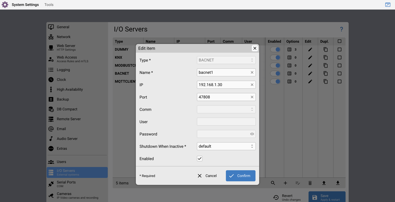
A BACnet I/O Server's Settings page
Step 2: Configure the BACNETSERVER I/O Server
Add a second I/O Server of type BACNETSERVER:
-
ID: bacserv
-
IP Address: broadcast address of the second network, for example
192.168.2.255 -
IP Port: leave blank to use the default port 47808
This is the I/O Server through which third-party systems on the second network connect to HSYCO and read values.
Save and restart HSYCO.
Step 3: Add a Keypad in the Project Editor
Open the Project Editor and add a Keypad object to your page. Set its attributes:
| Attribute | Value |
|---|---|
| Name | $bacnet_setpoint |
| Decimals | 1 |
| Label | Setpoint |
Because the Name starts with $, HSYCO automatically stores the typed value in the variable $bacnet_setpoint when the user confirms.
Save the project.
Step 4: Write the EVENTS rules
Open the Code Editor of the BACNET Client, create a new EVENTS file, and write:
# When the user types a value, write it to the external BACnet device
$bacnet_setpoint : IO bac.3.analogoutput.10 = writeproperty/14:presentvalue: $bacnet_setpoint
# Also expose the value on HSYCO's own BACnet server, for the second network
$bacnet_setpoint : IO bacserv.analogvalue.0.presentvalue = $bacnet_setpoint
The space before $bacnet_setpoint in each rule is required so the EVENTS interpreter replaces the variable name with its numeric value.
The second rule writes the same value into HSYCO's own internal analogvalue object instance 0. If that object does not exist yet, HSYCO creates it automatically as a dynamic object. An external BACnet client on the second network can then read analogvalue instance 0 from HSYCO using a standard readproperty:presentvalue request.
10.4 MQTT
10.4.1 Protocol Overview
MQTT is a lightweight messaging protocol built around a publish/subscribe mode. Instead of devices talking directly to each other, they communicate through a central broker: publishers send messages to the broker on a topic, and subscribers receive messages from the broker on topics they have registered interest in. This makes it particularly well suited for IoT sensors, smart home devices, and any scenario where many small devices need to exchange data efficiently.
HSYCO covers both sides of MQTT through two separate I/O Server types. With MQTTBROKER, HSYCO itself becomes the broker, external MQTT devices connect to HSYCO and exchange messages through it. With MQTTCLIENT, HSYCO connects as a client to an external MQTT broker, publishing and subscribing to topics on that broker.
Both I/O Servers fully support MQTT version 3.1.1 (Figure 42).
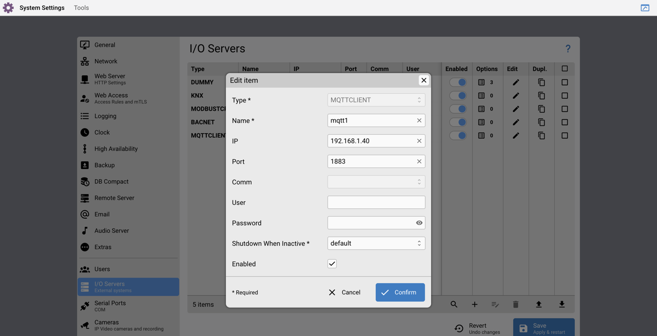
An MQTTCLIENT I/O Server's Settings page
10.4.2 HSYCO as an MQTT Broker
Configuration
Add an MQTTBROKER I/O Server in Settings. Unlike most other I/O Servers there is no IP address to configure, HSYCO listens for incoming client connections on its own network interfaces.
The available options are:
| Option | Default | Description |
|---|---|---|
startupevents | true | Generate IO events during the driver's start-up phase. When false, events are generated only after HSYCO is aligned with the current status of the system. |
acceptunknown | false | When true, accept connections from clients whose ID is not specified in mqttbroker.ini. When false, only known clients can connect. |
localport | 1883 | Local port for incoming client connections. |
maxthreads | 64 | Maximum number of clients connected simultaneously. |
Authentication
Authentication is optional. If you set a default username and password in Settings, those credentials will be used by the authentication mechanism. If no default credentials are set, authentication is disabled entirely.
For per-client credentials, create a file named mqttbroker.ini in the HSYCO root directory. Each line represents one client. The clientid is required; username and password are optional:
client123:username=homesensor,password=abc123
client123:password=abc123,username=homesensor
client123:username=homesensor
client123:password=abc123
client123
Client identifiers are case-insensitive; MQTT_Client and mqtt_client are treated as the same identifier and cannot both be registered.
Datapoints
The MQTTBROKER I/O Server exposes these datapoints (all prefixed with the I/O Server ID):
| Datapoint | Value | R/W | Description |
|---|---|---|---|
connection | online | R | The broker is ready to accept client connections |
offline | R | The broker failed to start | |
client.<clientId>.connected | 1 | R | <clientId> is connected to the broker |
0 | R | <clientId> is not connected | |
client.<clientId>.publish.<topicName> | <message> | R | <clientId> published a message on <topicName> |
client.<clientId>.willpublish.<topicName> | <message> | R | The broker published <clientId>'s will message on <topicName> after a connection problem |
client.<clientId>.lastseen | <timestamp> | R | Time of the last message or ping from <clientId> |
client.<clientId>.subscribe.<topicName> | subscribed, <n> | R | <clientId> subscribed to <topicName> with QoS <n> |
unsubscribed | R | <clientId> unsubscribed from <topicName> | |
publish.<topicName> | <message> | R/W | Publish a message on <topicName>, or read the last one published |
10.4.3 Recipe: MQTT Integration with KNX
This recipe shows how to bridge HSYCO MQTT and KNX: publish KNX device changes to MQTT topics, and respond to MQTT messages by controlling KNX devices.
Prerequisites:
-
MQTTBROKER I/O Server configured with ID
mqtt -
MQTT client with ID
knx_clientconnected to the broker -
KNX I/O Server configured
The code:
# When KNX group 1/2/3 turns on, publish a message to MQTT topic
IO knx.1/2/3 = 1 : IO mqtt.publish.my-topic/output1/val = 1
# When KNX group 4/5/6 changes, publish its new value to MQTT
IO knx.4/5/6 : IO mqtt.publish.my-topic/output2/val = IO knx.4/5/6
# When MQTT client knx_client publishes to a topic, update KNX group 7/8/9
IO mqtt.client.knx_client.publish.my-topic/input1/val = 1 :
IO knx.7/8/9 = 1
Important Notes:
-
MQTT topic names are case-insensitive and converted to lowercase
-
Spaces in topic names are replaced with underscores (e.g.,
my topicbecomesmy_topic) -
The datapoint format is:
mqtt.publish.<topicName>(to publish FROM HSYCO) -
To receive from a client:
mqtt.client.<clientId>.publish.<topicName> -
Replace
knx_clientwith your actual MQTT client ID
10.5 LoRaWAN Integration
10.5.1 Protocol Overview
LoRaWAN is a long-range, low-power wireless protocol designed for sensors and devices that need to send small amounts of data over long distances, infrequently, without wires.
The LoRaWAN I/O Server implements both a LoRaWAN Network server and an Application server, so HSYCO can manage a LoRaWAN 1.0.4 network on its own.
Here's how the pieces fit together:
-
HSYCO acts as a server for one or more LoRaWAN gateways.
-
Gateways must be configured as standard Semtech packet forwarders. This is the industry-standard way gateways forward radio data to a network server.
-
Communication between the gateways and HSYCO happens over UDP.
-
The implementation follows the Semtech packet forwarder protocol v4.0.1 and supports both Class A and Class C end devices.
In short: your LoRaWAN gateways collect radio data from sensors and forward it to HSYCO over the network. HSYCO then makes that data available as datapoints you can use in EVENTS, just like any other I/O Server.
10.5.2 Configuring the LoRaWAN I/O Server
The LoRaWAN I/O Server is added like any other I/O Server, from the I/O Servers section of Settings.
A few things to know before you start:
-
Only one instance of the LoRaWAN I/O Server is allowed per HSYCO installation.
-
Licensing: the LoRaWAN I/O Server consumes one item from the I/O Servers license total for each gateway you configure.
-
By default, the server starts in automatic discovery mode, listing any gateway or device it hears from; you'll configure this properly using the LoRaWAN Utility in the next sections.
Options
There is also a High Availability setting, Shutdown when inactive, which defaults to true.
10.5.3 Configuring Gateways
Once the I/O Server is running, the gateways themselves need to be pointed at HSYCO.
Gateways forward the data frames they receive from end devices to HSYCO. To make this work, configure each gateway as a standard Semtech packet forwarder, using:
-
HSYCO's IP address, and
-
the port number set in the
localportoption (1700 by default).
| Option | Default | Values | Description |
|---|---|---|---|
localport | 1700 | <port_number> | The IP port HSYCO uses locally to listen for incoming UDP packets from the gateways. |
downlinkpower | — | 2 … 20 | Default power value for downlink frames. |
debug | false | true / false | Print debugging information to the logs. |
Depending on your network, you may also need to open a port-forwarding rule on your router so that LoRaWAN traffic reaches HSYCO's IP address.
Once a LoRaWAN I/O Server is defined in HSYCO, the LoRaWAN Utility becomes available among the Manager's applications. Use it to discover and configure both gateways and devices.
10.5.4 Connecting Devices
With gateways in place, you can connect the LoRaWAN end devices (sensors, meters, and similar hardware) that will send data through them.
LoRaWAN devices support two activation modes:
-
OTAA (Over-The-Air Activation): the device joins the network dynamically using a DevEUI, JoinEUI/AppEUI, and AppKey.
-
ABP (Activation By Personalization): the device is pre-configured with fixed session keys (AppSKey and NwkSKey) and doesn't perform a join procedure.
Devices also have a Class: A or C are supported.
10.5.5 Recipe: Add a device with the LoRaWAN Utility
-
In the LoRaWAN Utility, select the Devices tab.
-
Enable the Auto-discovery checkbox. Devices transmitting within range of your configured gateways will appear in the list.
-
Click on a discovered device to open its configuration.
-
Set the ID (used for the device's datapoints,
dev.<id>.*, defaults to the device address), the Address, and the Class. -
Depending on the activation mode used by the device, fill in either the OTAA fields (DevEUI, JoinEUI/AppEUI, AppKey) or the ABP fields (AppSKey, NwkSKey). You can click Generate to create a random key to copy onto the device.
-
Save the device's configuration.
-
Once all devices are configured, click Commit to persist the configuration, the LoRaWAN I/O Server will restart with the updated setup. Each gateway and device appears with its own datapoints (Figure 43).
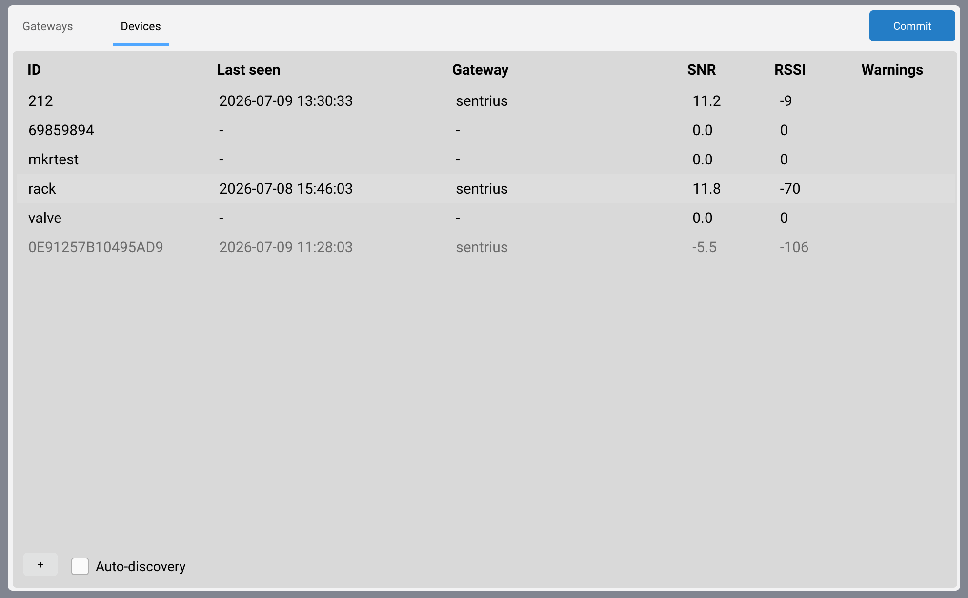
LoRaWAN gateway and device datapoints
10.5.6 Using LoRaWAN Data in EVENTS
Every gateway and device gets its own set of datapoints, named using a simple convention:
-
Gateway datapoints:
gw.<id>.* -
Device datapoints:
dev.<id>.*
As with any I/O Server, these are referenced with the I/O Server's name as a prefix, for example, if you named your server lora, a gateway's connection status is lora.gw.<id>.connection, and a device's data channel is lora.dev.<id>.data.ch<n>.
A couple of datapoints worth knowing right away:
-
gw.<id>.connectionreports online when the gateway is ready to receive packets, and offline otherwise, handy for checking that a gateway is alive. -
dev.<id>.data.ch<n>reports the value received on data channel<n>from a device.
10.5.7 Recipe: React to a device datapoint in EVENTS
Here's a documented example that reacts to data coming from a LoRaWAN device and forwards it to another datapoint:
#when a LoRaWAN device sends a temperature data, multiply * 10 then send to KNX
io lora.dev.212.data.ch101 : $temp212 = io lora.dev.212.data.ch101,
$temp212 * 10, $temp212 round 0,
io knx.4/5/6 = $temp212
This line triggers whenever device 212's channel 101 receives new data. Because this device is configured to use Cayenne data format (checked in its configuration), HSYCO automatically parses the incoming LoRaWAN payload into readable datapoints like lora.dev.212.data.ch101. Without Cayenne format, you would receive raw binary data requiring manual JSON parsing, which is outside the scope of this book.
You can use the same pattern to react to any LoRaWAN device datapoint, read the incoming value with io lora.dev.<id>.data.ch<n>, process it as needed, and pass it on to a UI object, a log entry, or another I/O Server, exactly as you would with any other datapoint in EVENTS.