Chapter 4: I/O Servers and Device Integration
In the previous chapters, you learned about HSYCO's architecture, installed the software, and explored the Manager tools. Now it's time to connect HSYCO to actual building automation systems.
This chapter introduces I/O Servers, the components that enable HSYCO to communicate with devices and protocols in your building. You'll learn how to configure connections, understand how datapoints work, and create complete working integrations through practical recipes. By the end of this chapter, you'll be able to add I/O Servers, configure communication parameters, and read and write data to real building automation devices.
4.1 I/O Server Fundamentals
Before connecting to specific protocols like KNX or Modbus, you need to understand how HSYCO communicates with building systems. This section covers the core concepts that apply to all I/O Servers: what they are, how datapoints work, and how to configure and test connections.
4.1.1 What Are I/O Servers?
An I/O Server is the logical representation of a field system integrated in HSYCO. A field system can be a security system, a BUS network, or even something more abstract like weather information gathered from the Internet or any system with an integration API or integration protocol.
Each I/O Server you configure represents one connection. A KNX I/O Server connects to a KNX/IP gateway and communicates with all devices on that KNX installation. A Modbus I/O Server connects to a Modbus TCP gateway or RTU device. A BACnet I/O Server connects to BACnet/IP devices on your network.
You can configure multiple I/O Servers of the same type. If you have two separate KNX installations, you configure two KNX I/O Servers, each with its own ID and connection parameters.
4.1.2 The I/O Server ID
When you create an I/O Server, you assign it a unique ID. This ID is used throughout HSYCO to reference the I/O Server and its data. For example, if you create a KNX I/O Server with the ID knx, all datapoints from that server will begin with knx. The ID must be unique across all I/O Servers. You cannot have two I/O Servers with the same ID, even if they are different types.
4.1.3 How I/O Servers Communicate
I/O Servers communicate with field systems using the native protocol of each system. You configure the communication parameters in Settings:
For network-based protocols (KNX/IP, Modbus TCP, BACnet/IP), you specify an IP Address and IP Port. For serial protocols (Modbus RTU), you specify a Comm ID that identifies the serial port.
Once configured and started, the I/O Server establishes the connection and begins exchanging data with the field system. The connection status is available through a special datapoint called connection, which reports online when connected and offline when the connection fails.
4.2 Understanding Datapoints
All I/O Servers provide datapoints through which they receive commands and trigger events. A datapoint represents a piece of data from the field system: the state of a light, the value of a temperature sensor, the position of a blind.
A datapoint is identified by the combination of the I/O Server ID and the datapoint ID, using the format <io_server_id>.<datapoint_id>. If you have a KNX I/O Server with the ID knx and a datapoint called 0/0/1, the complete datapoint identifier is knx.0/0/1.
4.2.1 Readable and Writable Datapoints
A datapoint can be readable (R), writable (W), or both. Here is an example datapoint table from an I/O Server named iOS:
ios.foo can be read (values 1 or 2) and written to with reset. ios.bar can be read in three states (a, b, unknown) and written with a or b.
| ID | Value | R/W | Description |
|---|---|---|---|
foo | 1 | R | the datapoint reads 1 |
2 | R | the datapoint reads 2 | |
reset | W | write reset to the datapoint | |
bar | a | R, W | read as, or set to, a |
b | R, W | read as, or set to, b | |
unknown | R | the datapoint reads unknown |
4.2.2 Reading Datapoints
The main use for readable datapoints is to execute actions when they trigger an event. In EVENTS:
IO ios.foo = 1 : LOG = "Foo changed to 1"
You can also read the current value of a datapoint at any time and pass it to other actions:
TIME = 0800 : $var = IO ios.bar
TIME = 0800 : UISET object.text = IO ios.bar
Events are generally triggered whenever a readable datapoint's value changes. Some datapoints may trigger events even if the value is unchanged, depending on the behavior of the field system.
4.2.3 Writing Datapoints
Writable datapoints are used to send commands to the field system. In EVENTS, you use the IO action:
USER mybutton : IO ios.bar = a
Commands are queued and executed as soon as the I/O Server is ready to process them.
4.2.4 Commands vs State: An Important Distinction
If a datapoint is both readable and writable, writing a value to it does not mean that a subsequent reading will yield the same value. Writing to a datapoint issues a command to the I/O Server.
After setting a datapoint representing a light to on, you will continue reading its value as off until the field system notifies HSYCO that the light is actually on. Commands are what you want to happen; state is what actually happened.
Example: A Complete Datapoint Workflow
Here's a practical example showing the complete workflow:
-
A KNX light has datapoint
knx.0/0/1; the light is off, so the value is0. -
You send:
IO knx.0/0/1 = 1. -
HSYCO sends the command to the KNX system.
-
The KNX device receives the command and turns on the light.
-
The KNX device sends feedback to HSYCO.
-
HSYCO updates the datapoint value to
1. -
The event
IO knx.0/0/1 = 1fires.
4.3 Adding I/O Servers in Settings
To connect HSYCO to a building automation system, you add an I/O Server through the Settings application in the Manager.
4.3.1 Opening I/O Servers Configuration
-
Open the Manager.
-
Click Settings from the application list.
-
Select I/O Servers from the left sidebar.
You'll see a list of all configured I/O Servers. If this is your first time, the list will be empty.
4.3.2 Adding a New I/O Server
To add a new I/O Server:
-
Click on the + icon at the top of the I/O Servers list.
-
A dialog appears asking you to select the server type and enter an ID (Figure 17). The ID must not contain capital letters, spaces, or special characters.
Common server types include KNX, MODBUSTCP, MODBUSRTU, and BACNET. Choose a short, descriptive ID, for example, knx for a KNX system or modbus for a Modbus connection.
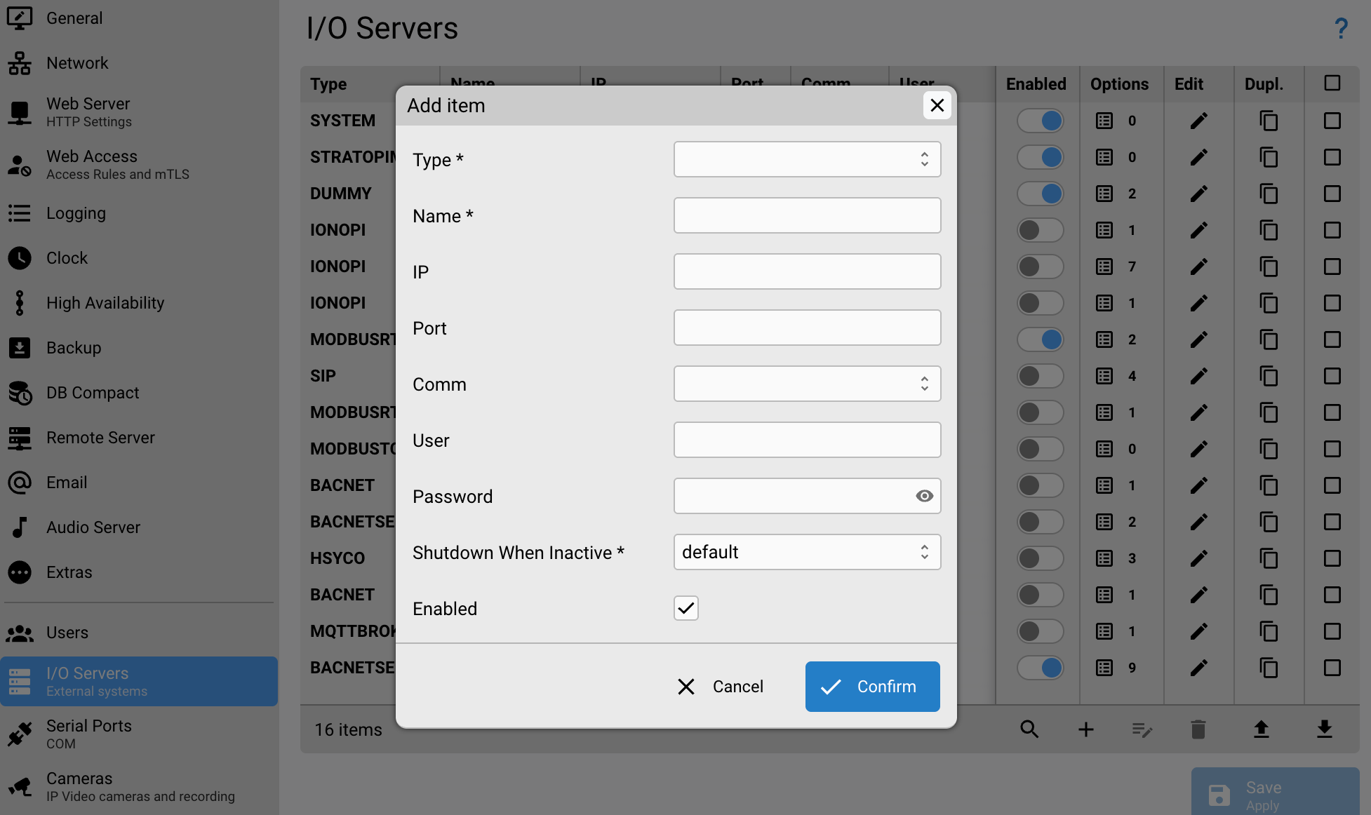
Settings → I/O Servers: the add I/O Server dialog
4.3.3 Configuring Communication Parameters
The most common parameters are:
-
IP Address: The IP address of the gateway or device. For example, 192.168.1.100 for a KNX/IP gateway, or 192.168.1.255 (broadcast address) for BACnet/IP
-
IP Port: The TCP or UDP port number. Leave blank to use the default port for the protocol (for example, 3671 for KNX, 502 for Modbus TCP, 47808 for BACnet)
-
Comm ID: Select the communication port the device is connected to. You must first configure the serial port in the Serial Ports section of Settings before it appears in this list
4.3.4 High Availability Settings
The Shutdown when inactive parameter is relevant only in High Availability configurations with a master and slave HSYCO server. Set to true to stop the I/O Server when this server is not active; set to false to keep it running. For most installations, leave this at the default value.
4.3.5 Options
Each I/O Server type has specific options that control its behavior. Common options include:
-
startupevents: Controls whether the I/O Server generates events during the startup phase, or only after HSYCO is fully aligned with the field system
-
discovery: Enables automatic discovery of devices and automatic population of the catalog.json device list (see Chapter 12)
-
eventslog: Controls whether events from this I/O Server are written to the log files
Refer to the protocol-specific sections in this chapter for details on the options available for each I/O Server type.
4.4 Testing Connections
After adding an I/O Server and restarting HSYCO, verify that the connection is working correctly.
4.4.1 Checking the Connection Datapoint
Every I/O Server provides a connection datapoint that reports:
-
online: HSYCO successfully connected to the field system
-
offline: HSYCO cannot connect to the field system
To check it: open Status Browser, search for your I/O Server ID (e.g. knx), and look for the connection datapoint.
4.4.2 Common Connection Problems
If the connection datapoint shows offline, check:
-
IP Address: Verify the IP address is correct. Can you ping the device from HSYCO server?
-
IP Port: Verify the port number is correct for the protocol.
-
Network: Ensure the device and HSYCO server are on the same network or can route to each other.
-
Firewall: Check that firewalls aren't blocking the connection.
-
Device Configuration: Verify the device or gateway is configured to accept connections.
-
Logs: Check the HSYCO log files for error messages. Open Log Viewer in the Manager and look for messages from the I/O Server.
4.4.3 Reading Initial Datapoint Values
Once the connection is online, verify that datapoints are working by reading their values in Status Browser. Search for your I/O Server ID and look at the Value column. For a light datapoint, you might see 0 (off) or 1 (on).
4.4.4 Testing Write Operations
To test writing to a datapoint, add a temporary EVENTS rule:
TIME = 1423 : IO knx.light.1 = 1
Save the EVENTS file, wait for the time event to fire, verify the device responds, and check Status Browser to confirm the datapoint value updates. Then remove the test rule.
4.4.5 Using the Log Viewer
Log Viewer shows real-time events from I/O Servers. Open it from the Manager, enable the Events log level, and watch for messages from your I/O Server. When a datapoint changes, you will see an event logged. When you send a command, you will see it appear in the log.
4.5 Your first I/O Server: DUMMY
The DUMMY I/O Server is the ideal starting point because it requires no physical hardware. Instead of connecting to real building automation devices, DUMMY creates virtual devices you can use for learning, testing, and prototyping : lights, dimmers, and blinds without any equipment.
4.5.1 The DUMMY I/O Server
The DUMMY I/O Server is a virtual server that simulates basic lighting and automation devices without connecting to any external system. When you turn on a DUMMY light, HSYCO updates the datapoint value exactly as it would if a real light had turned on; the behavior is identical, only the hardware is absent.
DUMMY supports three types of devices:
-
Lights: Simple on/off switches that can be in two states: 0 (off) or 1 (on)
-
Dimmers: Variable brightness lights that can be set to any level from 0% to 100%
-
Automations: Motorized devices like blinds or shutters that can move up, down, or stop
The DUMMY I/O Server does not count against your I/O Servers license total.
Generic Datapoints
Beyond lights, dimmers, and automations, DUMMY also supports arbitrary generic datapoints: named values you write and read directly from EVENTS, for example IO dummy.mode = away and later $m = IO dummy.mode. They are both readable and writable, which makes them well suited to the virtual flags and intermediate values mentioned in Section 4.5.6. Generic datapoint names must not begin with light, dimmer, or autom, and any space characters in the name are removed.
4.5.2 Recipe: Configuring the DUMMY I/O Server
This recipe walks you through adding and configuring the DUMMY I/O Server for the first time.
Step 1: Open Settings
Navigate to your HSYCO Manager and click Settings.
Step 2: Navigate to I/O Servers
In the left sidebar, select I/O Servers.
Step 3: Add the DUMMY I/O Server
Click the + icon. From the Type dropdown, select DUMMY. In the ID field, enter dummy. Click OK.
Step 4: Configure Options
After adding the DUMMY server, you'll see its configuration page (Figure 18). The DUMMY I/O Server has several options that control how many virtual devices it creates:
-
lights: Number of on/off light devices to generate (default: 0)
-
dimmers: Number of dimmer devices to generate (default: 0)
-
automations: Number of automation devices to generate (default: 0)
For this example configure: lights = 5, dimmers = 3, automations = 2.
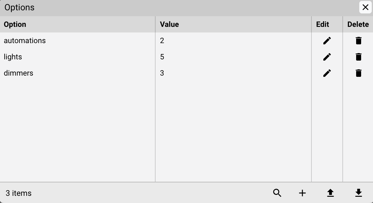
The DUMMY I/O Server options page
Note: DUMMY has a couple of more advanced options beyond this cookbook's scope: commandstate enables command/state mode, which decouples a datapoint's feedback state from the command sent to it (adding .cmd and .state suffixed datapoints for each writable datapoint), and httpcallpassword enables an HTTP API for triggering commands from outside EVENTS. See docs.hsyco.com's DUMMY reference for details.
Step 5: Confirm Discovery Is Enabled
Confirm that discovery is set to true (this is the default). This tells HSYCO to automatically populate the device list with the virtual devices, making them available in the Project Editor for user interface development.
Step 6: Save and Restart
Click Save at the bottom of the Settings page.
Click Restart to restart HSYCO and activate the DUMMY I/O Server.
After HSYCO restarts, your DUMMY I/O Server is running.
Step 7: Register the Datapoints in Catalog
New datapoints created by an I/O Server's device-count options, like DUMMY's lights, dimmers, and automations, don't appear in Status Browser until you open Catalog from the Manager and click Save. Do this once and your DUMMY I/O Server is ready to use.
4.5.3 Recipe: Creating Virtual Lights
Now that the DUMMY I/O Server is configured, let's work with virtual lights. This recipe shows you how to control on/off lights using the EVENTS programming language.
Understanding DUMMY Light Datapoints
Light datapoints follow the pattern dummy.light.n, where n runs from 1 to the number you configured. Each supports these values:
-
0 or off: The light is off
-
1 or on: The light is on
Step 1: Verify Lights in Status Browser
Open Status Browser and search for dummy. You should see dummy.light.1 through dummy.light.5, all showing 0.
Step 2: Turn On a Light with EVENTS
Open Code Editor, click EVENTS file, and add:
INIT : IO dummy.light.1 = 1
Save the file. Return to Status Browser, dummy.light.1 should now show 1.
Step 3: React to Light Changes
You can create automation logic that responds when a light changes state. Add these lines to your EVENTS file:
IO dummy.light.1 = 1 : IO dummy.light.2 = 1
IO dummy.light.1 = 0 : IO dummy.light.2 = 0
Whenever light 1 turns on, light 2 turns on. When light 1 turns off, light 2 turns off.
Step 4: Test the Logic
Add a toggle command:
USER toggle.light1 : IO dummy.light.1 = 0,
IO dummy.light.1 = 1
Trigger this USER event from a button or Status Browser and watch light 2 follow light 1.
4.5.4 Recipe: Creating Virtual Dimmers
Dimmers support variable brightness levels, which adds more flexibility than simple on/off lights.
Understanding DUMMY Dimmer Datapoints
Dimmer datapoints follow the naming pattern dummy.dimmer.n. Each supports these values:
-
0 or off: The dimmer is off
-
1 or on: Turn the dimmer on to its last level
-
1% through 100%: Set the dimmer to a specific brightness level
Like lights, dimmers are both readable and writable.
Step 1: Verify Dimmers in Status Browser
Open Status Browser and search for dummy. You should see dummy.dimmer.1, dummy.dimmer.2, and dummy.dimmer.3, all showing off (a fresh dimmer reads off, not 0, until it has been set to a level).
Step 2: Set Dimmer Levels
Open Code Editor, click EVENTS file, and add:
INIT : IO dummy.dimmer.1 = 50%,
IO dummy.dimmer.2 = 75%,
IO dummy.dimmer.3 = 100%
Save the file. In Status Browser you will see dummy.dimmer.1 = 50, dummy.dimmer.2 = 75, dummy.dimmer.3 = 100. Percentage values are stored as integers: 50 means 50%.
Step 3: Create Dimmer Control Logic
You can create rules that adjust dimmer levels based on conditions:
IO dummy.light.1 = 1 : IO dummy.dimmer.1 = 100%
IO dummy.light.1 = 0 : IO dummy.dimmer.1 = 25%
This sets dimmer 1 to full brightness when light 1 turns on, and dims it to 25% when light 1 turns off.
Step 4: Understanding On Commands
When you send on to a dimmer, it turns on to the last level it held before being turned off. Try this sequence:
TIME = 1000 : IO dummy.dimmer.1 = 75%
TIME = 1001 : IO dummy.dimmer.1 = off
TIME = 1002 : IO dummy.dimmer.1 = on
At 10:00 the dimmer is set to 75%. At 10:01 it turns off. At 10:02 the on command restores it to 75%.
4.5.5 Recipe: Creating Virtual Automations (Blinds)
Automations simulate motorized devices like blinds, shutters, or gates. They have movement states and positions rather than simple on/off values.
Understanding DUMMY Automation Datapoints
Automation datapoints follow the naming pattern dummy.autom.n.
-
up: The automation is moving upward (opening)
-
down: The automation is moving downward (closing)
-
stop or 0 or off: Stop the automation
-
offup: The automation is stopped in the upper position (fully open)
-
offdown: The automation is stopped in the lower position (fully closed)
Step 1: Verify Automations in Status Browser
Open Status Browser and search for dummy. You should see dummy.autom.1 and dummy.autom.2, both showing unknown; a fresh automation reads unknown until it receives its first command, rather than defaulting to offdown.
Step 2: Move an Automation
Open Code Editor, click EVENTS file, and add:
USER open.blind1 : IO dummy.autom.1 = up
USER close.blind1 : IO dummy.autom.1 = down
USER stop.blind1 : IO dummy.autom.1 = stop
Step 3: Understanding Movement Timing
The automationsontime option controls how long automations take to complete a full movement. The default is 30; virtual automation devices automatically switch to offup or offdown 30 seconds after receiving an up or down command.
With the default of 30 seconds, sending up produces this sequence:
offdown → up (moving) → offup (fully open) after 30 seconds.
If automationsontime is set to 0, the device remains in the up or down state indefinitely — it never automatically transitions to offup or offdown. This is useful when you want to control the final state explicitly from EVENTS rather than relying on automatic timing.
To change this setting: in Settings → I/O Servers → dummy, set automationsontime = 0, then save.
Step 4: Create Automation Logic
You can create rules that coordinate multiple automations:
IO dummy.light.1 = 1 : IO dummy.autom.1 = up,
IO dummy.autom.2 = up
IO dummy.light.1 = 0 : IO dummy.autom.1 = down,
IO dummy.autom.2 = down
This opens both blinds when light 1 turns on, and closes them when light 1 turns off.
4.5.6 Understanding Persistent State Mode
By default, when HSYCO restarts, all DUMMY datapoints are deleted and re-initialized. Lights return to off, dimmers to 0, and automations to offdown.
In persistent mode, all existing datapoints are retained and reset to their last value at startup. HSYCO saves data to the local database storage (in the data directory) every 60 seconds, not immediately, so a value set in the last minute before an unexpected shutdown may not be retained.
Enabling Persistent State Mode
Go to Settings → I/O Servers → dummy, add the option persistent = true, then save. HSYCO restarts with persistent mode active.
How It Works
With persistent mode enabled, a dimmer set to 75% will restore to 75% after HSYCO restarts. The startupevents option (default true) controls whether IO events fire for persistent datapoints during startup — when enabled, EVENTS rules watching those datapoints trigger at startup with their restored values.
If a DUMMY I/O Server that was previously running in persistent mode is restarted with persistent = false, all retained datapoints are discarded and the server starts fresh.
When to Use Persistent Mode
Persistent mode is useful when you use DUMMY datapoints as virtual flags or intermediate values in complex automation scenarios where those values must survive restarts. For pure learning and testing, the default non-persistent mode is simpler.
4.6 Weather Information - WXONLINE
The WXONLINE I/O Server provides weather information and forecasts retrieved from OpenWeatherMap. It connects to the OpenWeatherMap service via the Internet and updates weather data at regular intervals, creating read-only datapoints for current conditions and five-day forecasts.
Like DUMMY, the WXONLINE I/O Server does not count against your I/O Servers license total.
4.6.1 Recipe: Configuring the WXONLINE I/O Server
Getting an OpenWeatherMap API Key
Before you can use WXONLINE, you need an API key from OpenWeatherMap.
-
Go to
https://home.openweathermap.org/users/sign_upand register. -
Verify your email address.
-
Log in and navigate to
https://home.openweathermap.org/api_keys. -
Copy the default API key already created for your account.
If you do not specify a key in HSYCO, a default key will be used, but the pollinterval option will not allow values below 60 minutes.
Tip: Keep your API key private.
Step 1: Add the WXONLINE I/O Server
Open Settings → I/O Servers and click +. Select WXONLINE as the type and enter weather as the ID. Click OK.
Step 2: Configure Options
The available options are:
Set key to your OpenWeatherMap API key and pollinterval to 10.
Step 3: Set Your Location
The location option is required. You can specify it in two ways:
Using a city ID: Download the location list from http://bulk.openweathermap.org/sample/city.list.json.gz , extract it, and search for your city. The id field is what you need. For Milan, Italy: location = 3173435.
Using coordinates: Specify latitude and longitude in decimal degrees using the format <latitude>:<longitude>. For Milan: location = 45.461001:9.183567.
Step 4: Save Configuration
Click Save. HSYCO restarts and the WXONLINE I/O Server begins retrieving weather data.
4.6.2 Recipe: Reading Current Weather Data
Once WXONLINE is configured and running, it creates datapoints for current weather conditions. This recipe shows you how to access this data.
| Option | Default | Values | Description |
|---|---|---|---|
location | — | <id> or <lat>:<lon> | Required. Target location ID or coordinates |
key | — | <key> | OpenWeatherMap API key |
pollinterval | 10 | n >= 10 | Data acquisition interval, in minutes |
gui | true | true / false | Enable the UI object and UISET actions |
Note: Almost all WXONLINE datapoints are read-only. The one exception is location, which you can write to at runtime to retarget the forecast, useful for a mobile installation.
Step 1: Verify the Connection
Open Status Browser and search for weather. Find weather.connection, it should show online. If it shows offline, check your API key and location settings, then review Log Viewer for error messages.
Step 2: View Current Temperature
In Status Browser, search for weather.temp.c (or weather.temp.f for Fahrenheit). Its value updates every pollinterval minutes, reflecting the current temperature at your configured location.
Step 3: Use Weather Data in EVENTS
You can create automation logic based on weather conditions. For example, to close blinds when it's sunny:
IO weather.condition = sunny : IO dummy.autom.1 = down,
IO dummy.autom.2 = down
Or to log the current temperature:
TIME = 1200 : $temp = IO weather.temp.c
| Datapoint | Description |
|---|---|
location | The target location name |
temp.c | Current temperature in Celsius |
temp.f | Current temperature in Fahrenheit |
humidity | Relative humidity, percentage |
pressure | Atmospheric pressure, in inHg (multiply by 33.86389 for hPa) |
wind.speed | Wind speed, in km/h |
wind.dir | Wind direction, in degrees |
condition | Weather condition description |
4.6.3 Recipe: Accessing Weather Forecasts
WXONLINE provides five-day forecasts. Forecast datapoints follow the pattern weather.forecast.property.n, where n ranges from 1 to 5.
Example: alert if tomorrow will be cold:
IO weather.forecast.temp.low.c.1 < 5 : IO telegram.message.all = "Tomorrow will be cold"
Example: prepare for rain:
IO weather.forecast.condition.precipitation.1 = 1 : IO dummy.autom.1 = down
Weather Condition Values
The condition and forecast.condition.n datapoints report conditions as text strings, drawn from a fixed vocabulary of around 45 values, including sunny, partly_cloudy, cloudy, showers, drizzle, freezing_rain, hail, thunderstorms, thundershowers, snow, snow_flurries, snow_showers, foggy, windy, tornado, tropical_storm, and unknown. There is no plain rain value.
Condition Categories
Because that vocabulary is large, WXONLINE also publishes category datapoints that group the conditions into the outcomes automations usually care about: condition.clear, condition.precipitation, condition.storm, condition.partly_cloudy, and condition.low_visibility, each reporting 1 or 0, plus a forecast.condition.<category>.n equivalent for each forecast day. Testing condition.precipitation = 1 is more reliable than enumerating every rain- and snow-related string by hand, which is why the "prepare for rain" example above uses forecast.condition.precipitation.1.
| Datapoint | Description |
|---|---|
forecast.day.n | Day of the week |
forecast.temp.low.c.n | Low temperature in Celsius |
forecast.temp.low.f.n | Low temperature in Fahrenheit |
forecast.temp.high.c.n | High temperature in Celsius |
forecast.temp.high.f.n | High temperature in Fahrenheit |
forecast.condition.n | Weather condition |